
Click subject below for report ▼
ANIMALS
with
Paul Reeves
BIRD BOX
with
Paul Reeves
BOWL
from a PLANK
with
Paul Reeves
BOWL TURNING TECHNIQUES
with
Paul Reeves
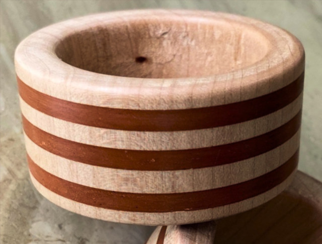
BOX of CONTRASTING WOODS
with Paul Reeves
BUTTONS
with Paul Reeves
CLOCKS in WOOD
with
Andy Ogilvie
COLOURING with a SPLASH
with Paul Reeves
GAVEL
with Paul Reeves
HANDLES & FEET
with Graham Turner
JEWELLERY with
Andy Ogilvie
and Paul Reeves
KILNER JARS
with
Andy Ogilvie
KITCHEN ITEMS
with
Paul Reeves
LIGHT BULBS in wood
with
Paul Reeves
MIXED SOLID MEDIA with
Andy
Ogilvie
MULTIPLE CENTRES TURNING
with
Paul Reeves
MUSHROOMS DECORATED
with
Paul Reeves
OFF-CENTRE
TURNING
with
Paul Reeves
OFF-SET BOWLS
with
Paul Reeves
PENCIL
SHOOTER
with
Paul Reeves
PLATES &
PLATTERS
with
Paul Reeves
PLYWOOD
with
Ed Walker
PODLETS
with
John Bolt
PUZZLES & TRICKS
with
Paul Reeves
SPHERE TURNING
with Paul Reeves
SPINDLE & FACE PLATE TURNED
with
Paul Reeves
SPINDLE revision
with
Paul Reeves
STRAIGHT
from the TOOL
with
Paul Reeves
STREPTOHEDRONS
with
Andy Ogilvie
THREAD CUTTING SCREW BOX & TAP
with
Paul Reeves
THREE POINT
BOWL
with Andy Ogilvie
TEXTURING
with
Paul Reeves
THREE LEGGED STOOL
with
Paul Reeves
TOOTHPICK HOLDER with
Paul Reeves
TOY CAR RACING
with
Andy Ogilvie
TREEN HAND-HELD MIRROR
with
Paul Reeves
TWO-PART STICK/LAMP + ADDED VALUE
with
Paul Reeves
UNNATURAL NATURAL EDGE
with
Paul Reeves
WOODEN WHISTLE
with
Paul Reeves
Click subject above for report ▲
Clocks
in
Wood
with
Andy Ogilvie
Thu 20th February 2025 at MWCC Club Night
Traditionally in horology, the term 'clock' was used for an instrument that sounded regular time periods, while one that didn't strike audibly was referred to as a 'timepiece', thus doing as it says and tells the time "peacefully".
Obviously the clock mechanism is
beyond the capabilities of the majority of us but the regular wood turning
Suppliers of accessories, plus the likes of eBay & Amazon ensure they are readily &
speedily available.
There are two basic mechanisms - Clock Movement, which come as an
enclosed mechanism fixed into the back of a clock face with a choice of shaft
lengths protruding
through to drive a choice of hands; all for typically <£10
(circa 2025)
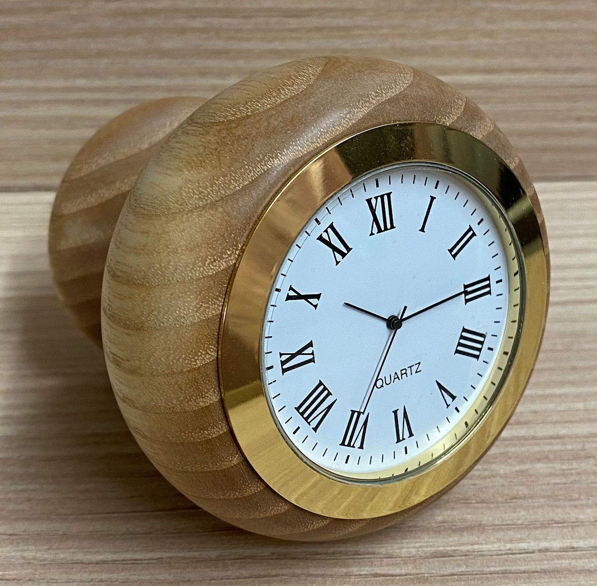
and Clock Insert, which are self contained working timepieces for typically
around £10 - £15 (circa 2025).
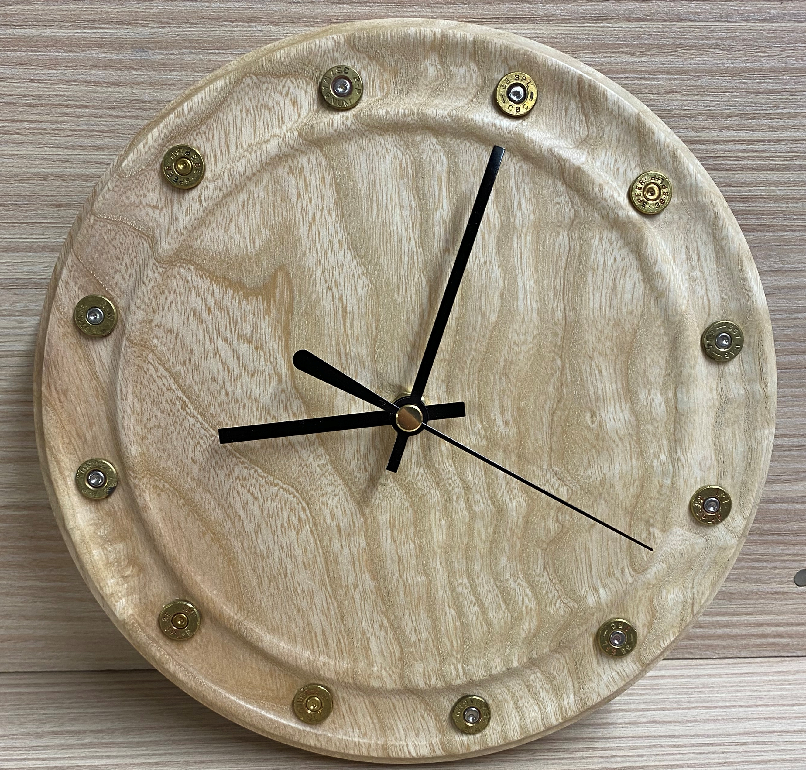
Below are some examples with added details like bullet cases or slotted brass
screws with slots aligned as hour markers.
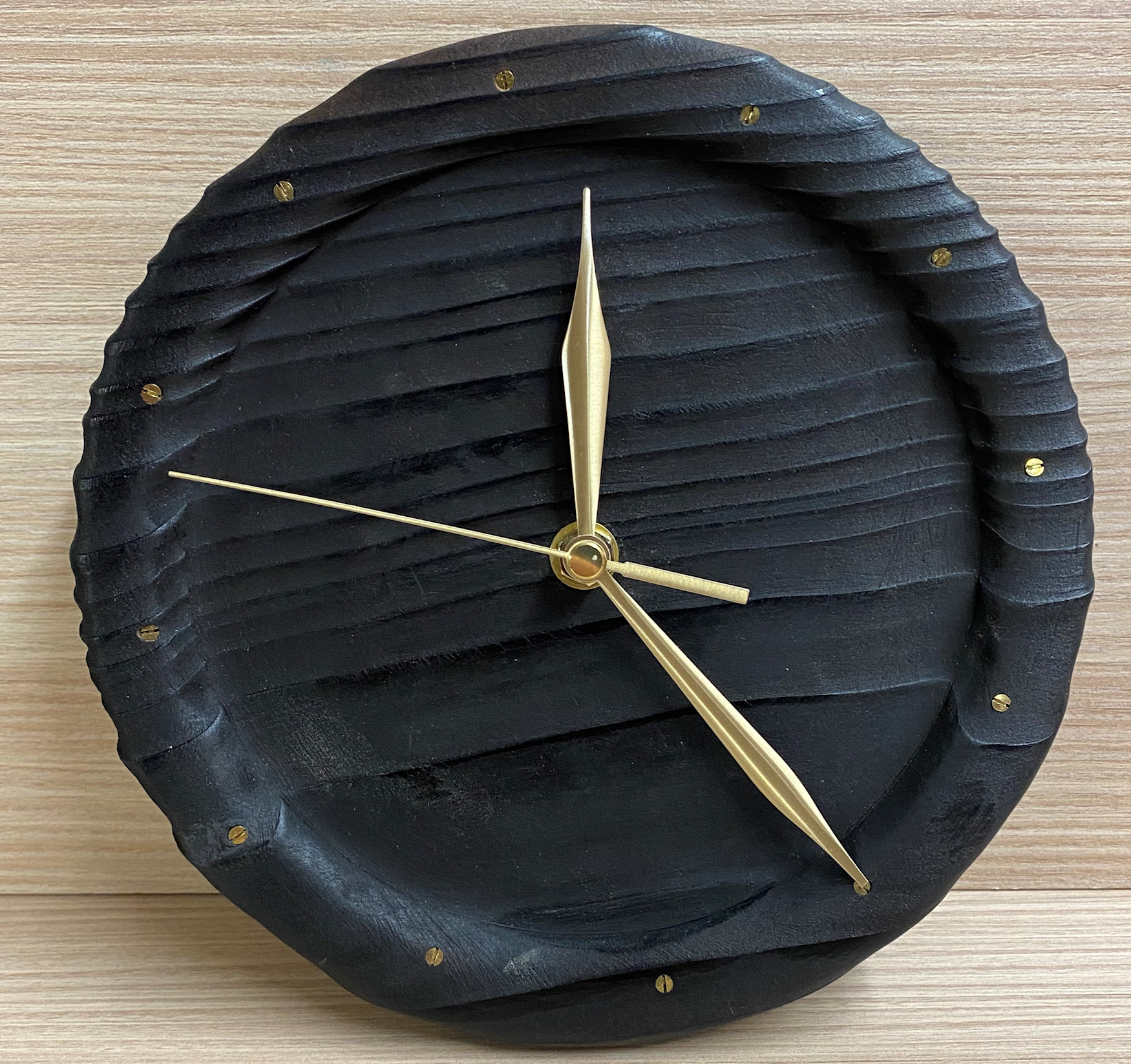
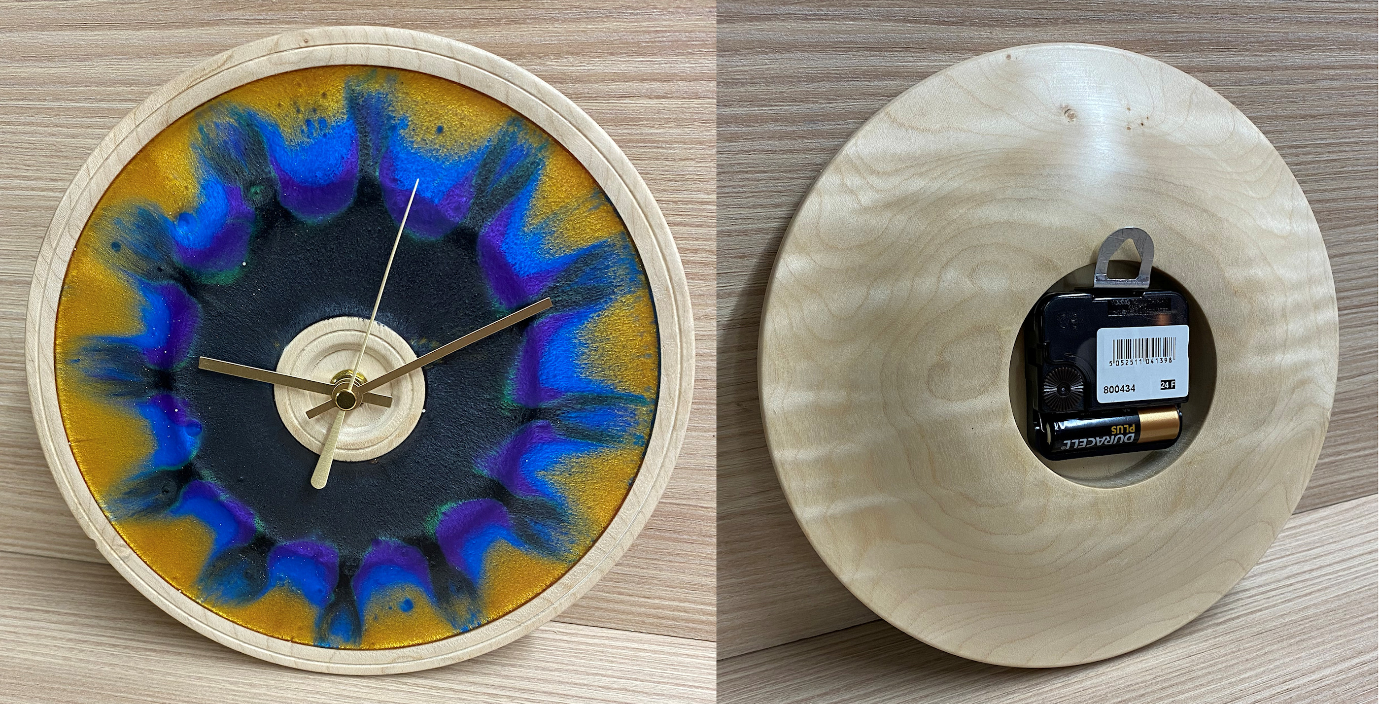
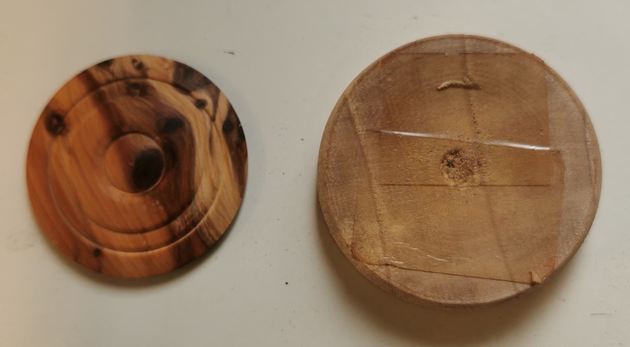
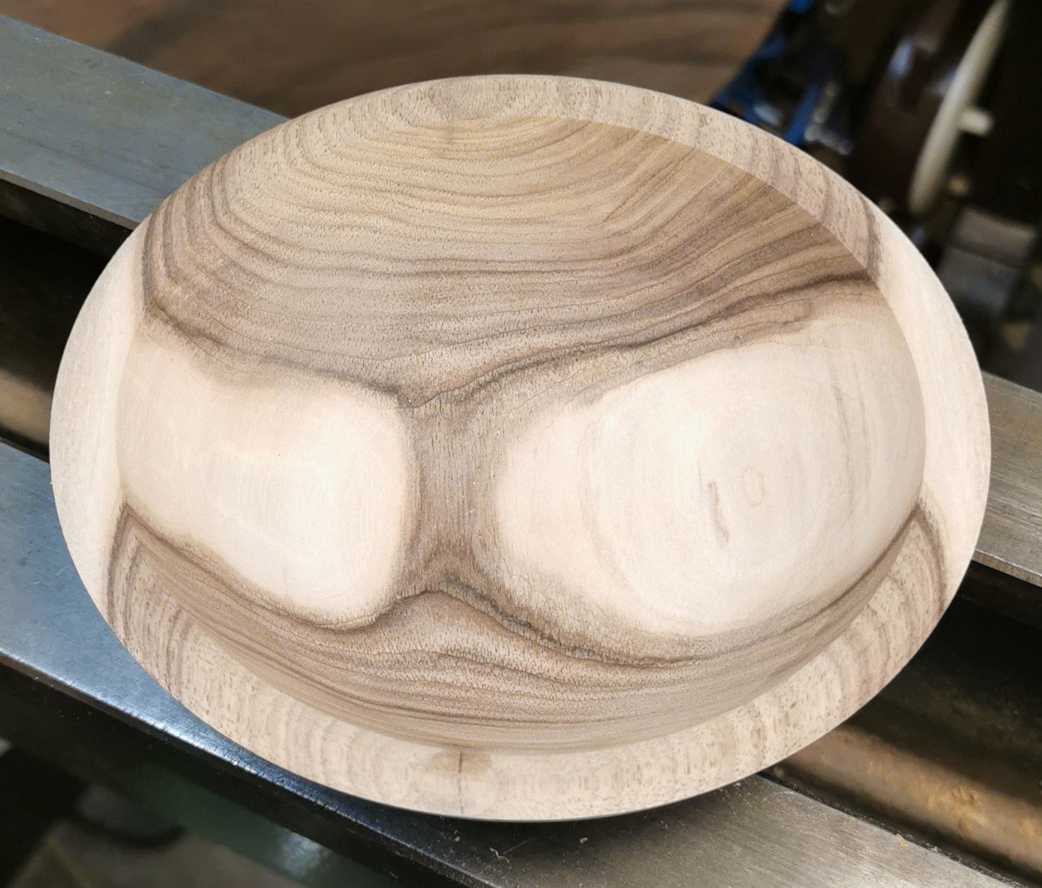
Tonight's design is a Timepiece with the Movement option to a platter-size blank of wood with expected interesting ripple and figure. The plan was to first work on its back to accommodate a recess for the mechanism, shape the rest then reverse the piece and deal with the front face which is of course what is in view most of the time.
Because a foot or screw holes would impair the finished
work, the blank had been prepared by being stuck onto a MDF Face Plate,
mysteriously using
a line of hot glue around the edge of where the rim touched the MDF.
Normally, half a dozen blobs of glue from a hot glue gun would suffice.
Top Tip
: Use clear polyethylene sticks (aka polythene) as they will
release the blank when heated with hot air from a hair dryer; other glue sticks
tend to bond
the MDF to all your hard work!
The blank had been turned to the round and a 8mm hole drilled dead centre for
the shaft driving the hands. This blank had some protective wax around its edges
so in case this reduced the effectiveness of the glue, Andy elected to use a nut
& bolt through the centre hole for assured security as a kind of 'bolt & braces'
precaution.
Each supplier of Movements invariably have different dimensions; Andy's example had the
following :-
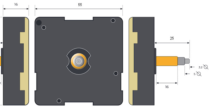
Having trued off the central section
of the back face, Andy wanted to turn a hole deep enough for the movement to fit
flush so that the timepiece would lie flat against the wall. The depth of the
Movement was 16mm (some kits may also have a rubber washer and thickness of
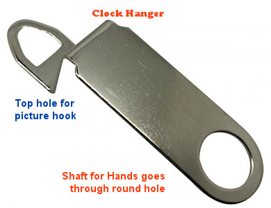
Clock Hangar to consider).
He found the correct radius to use by measuring the diagonal of the movement
case and dividing by two. He also had to consider room for the
shaft to extend through the front face sufficiently to allow the retaining nut
to have enough threads to fasten tight.
So
in his case, he needed the recess to be at least 16mm deep to ensure the
Movement didn't protrude out of the back and as the threaded extension is 16mm
(the 4mm thick nut can be countersunk into the face) the bottom also
needed to be at most 16mm from the front face. His trimmed blank was now 30mm
thick so the depth of the recess would have needed to be at least 14mm deep
for the hands to be clear of the face, thus a recess of 16 to 17mm satisfies both
requirements.
If your blank doesn't have enough depth for the movement to become flush with
the back face, you should find your Clock Mechanism includes a Clock Hanger
accessory for hooks which will resolve the problem.
Ordinarily, one could create the round hole at this stage. However, as Andy was using a nut & bolt through the centre hole as extra security, he elected to delay creating the recess for the movement until he had finished the shaping and could then safely remove the nut & bolt. One could mark in the calculated diameter using a set of dividers.
Ogee
Shaping
Andy wanted to give the piece some finesse and style rather than leave it as a
cylindrical block so opted to create an Ogee shape by a method advocated by
professional turner, Jimmy Clewes, (a Geordie but now operating
out of Western USA).
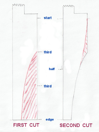 He
decided where the shape was going to start and then divided the distance to the
edge into thirds. The thickness of this blank was now 30mm, so Andy decided that
a finished edge thickness of about 12mm would look in proportion.
He
decided where the shape was going to start and then divided the distance to the
edge into thirds. The thickness of this blank was now 30mm, so Andy decided that
a finished edge thickness of about 12mm would look in proportion.
Working with just the outer two-thirds of the piece, his first cut was to turn
away a semi-parabolic shaped curve finishing at the 12mm mark at the outer edge.
He marked on this newly produced curve exactly halfway between the start and the
edge and for his second cut, carefully turned away the inner third section so
that the finished curve swept smoothly from the start to the halfway point.
With the shaping completed, Andy started to create the recess with a Parting Tool cutting from the earlier circular divider mark. Eventually he needed to remove the nut & bolt to finish the rest of the centre down to a level 18mm depth with the aid of a Box Cutter.
The back surface was sanded down to about 320 grit; a coat of Sanding Sealer was applied and allowed to dry before going over the sealed surface with the same 320 grit with a light touch before continuing with 400 grit. He applied some Chestnut Cut 'n Polish with the lathe stopped, then switched on the lathe and buffed to a shine whilst smoothing the timber at the same time. It dries almost immediately and can be over-coated with Friction Polish or wax for a higher shine.
Microcrystalline Wax
This type of wax has different methods of application
dependent upon
manufacturer. All of them have a melting point higher than
normal body temperature which helps to avoid finger marks,
but
Renaissance© Wax uses a precise proportion of
White Spirit which dissipates quickly and is best applied to the cool surface of
small areas at a time, which can then be buffed without waiting,
whereas :
other
microcrystalline waxes, eg Chestnut©
use alternative solvents that need about 20 minutes to dissipate to allow their
wax to form a dense coat. Because their constituents will dull while the solvent evaporates,
one needs to allow sufficient time for the solvent to disperse before
buffing.
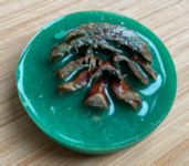
In order to work on the front face, Andy removed the piece from the faceplate using decorator's scraper and a mallet without the need of hot air. The mystery of his gluing method was revealed with the surprise that it had already been prepared as a multi-coloured resin face with hour graduations created by drawing contrasting colours out from the centre prior to it setting hard. This explains his method of gluing just the edge earlier in his demonstration because the resin surface was lower than the rim and wouldn't be in contact with the MDF.
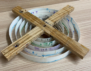 His
plan had been to have concentric circles of resin with Black in the middle, Green,
Purple, Blue and then Gold in the outside ring, using a frame (pictured
right). He had also prepared a paper
template with 12 hourly graduations placed underneath the timepiece in
preparation for when the frame was lifted away and a lollipop stick could be
dragged from the centre to the hour mark.
His
plan had been to have concentric circles of resin with Black in the middle, Green,
Purple, Blue and then Gold in the outside ring, using a frame (pictured
right). He had also prepared a paper
template with 12 hourly graduations placed underneath the timepiece in
preparation for when the frame was lifted away and a lollipop stick could be
dragged from the centre to the hour mark.
Unfortunately, this didn't work exactly as he had hoped but thought he would
highlight some errors of judgement for anyone who wished to try similar
themselves and get a better result.
The procedure took place on a bitterly cold day so Andy had abandoned his chilly garage workplace in favour of a warm Utility Room and warmed up his resins in hot water to ensure thorough mixing of resin, hardener & tint. This subsequently resulted in the resin mix being thinner & runnier than usual, which was more prone to creep under the dividers in the frame and more readily to mix/float/sink with its neighbouring colour when removing the frame. He also acknowledged that he needed to have left the mix to harden more before dragging the lollipop stick edge to form the graduations.
With the piece mounted by jaw expansion
onto the walls of the recess created for the movement, he
finished off the centre by providing a countersunk space for the thin retaining
nut so that it allowed the shaft to extend precisely
without the hands impeding the face, trued off all the high points and matched the rim edge
with the centre decorative detail.
The wooden parts of the face were sanded, and sanding sealer applied.
While dealing with the resin, it was important to go steadily through
considerably finer grits using all the intermediary grades with an increasingly
lighter touch to obtain an absolutely smooth surface. Alternative final
compounds could be cutting paste or even metal polish. The wood was finished
with Renaissance Wax.
There was now a choice of hanging
the Timepiece.
Andy had planned to have it flat against the wall, so he created a short upward
hole with a 8mm drill at the very top (in line with the 12 mark) of the flat
back above the Movement recess large enough for a picture hook to engage.
The alternative is to fit the aforementioned Clock Hanger.
(photos by Andy Ogilvie, Rick
Patrick & Paul Reeves)
<
Pencil
Shooter
with
Paul Reeves
Thu 16th January 2025 at MWCC Club Night 
The forceful characteristic needed to
propel a pencil is stretchiness, which can be obtained from elastic bands or springs.
The majority of online examples rely upon sawn shapes to provide strength for
supporting the stress & forces involved with taut rubber bands but as
Woodturners, we want predominantly turned components.
For this demonstration, Paul had chosen to use the energy provided from
releasing a compressed spring to fire a hexagonal pencil (doesn't
have to be a Reeves
pencil of course!) that is no larger than 8mm diameter.
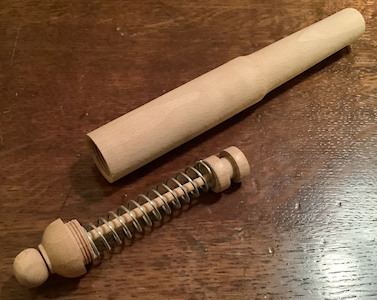
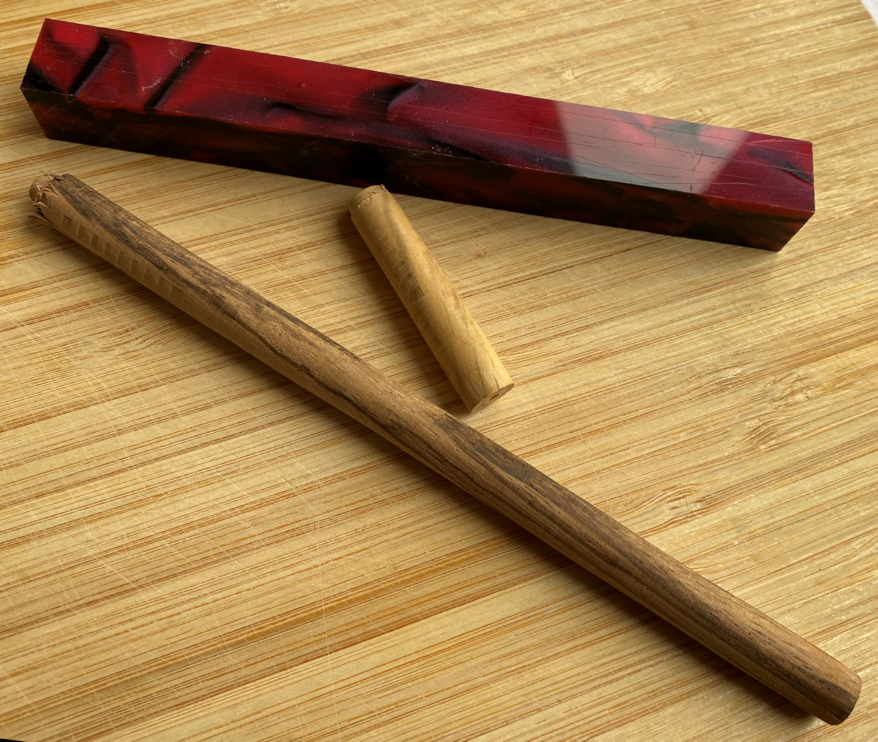
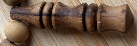
The 'weapon' shown below comprises of a Barrel with 2 bore sizes to accommodate
the 8mm pencil through the Muzzle end and 18mm bore through the Breech end. The
firing mechanism is a combination of Piston (with a notch for a trigger), the
Spring and a Rod through the Breech Cap to the Knob, which holds everything together.
Barrel
Paul decided to enlarge the first
10mm or so of the Barrel so that the Spring/Piston mechanism would clear all
threads whenever inserted or removed; this only needed the
Bore to be increased about 2 or 3mm with a Box Cutter.
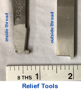 Next, a Relief Tool was used to
create a slot into the wall of the Barrel next to the step of the 18mm Bore
width. The thread is created with the Thread Chaser when it 'lands' and is
'taken off' in a smooth circular motion. That slot will allow freedom for the
Chaser to lift clear of the inside threads before it gets stopped suddenly
against the step down of width and would damage the threads already made.
Next, a Relief Tool was used to
create a slot into the wall of the Barrel next to the step of the 18mm Bore
width. The thread is created with the Thread Chaser when it 'lands' and is
'taken off' in a smooth circular motion. That slot will allow freedom for the
Chaser to lift clear of the inside threads before it gets stopped suddenly
against the step down of width and would damage the threads already made.
Beech doesn't often take a thread as well as some closer grain woods but in this
demonstration, a perfectly good thread was obtained with just half a dozen
passes without having to resort to wily ploys like stabilizing the wood grain
with thin superglue. The thread and bore were checked and any roughness
was dealt with by brush or abrasives.
The piece was reversed in the chuck
to expose the Muzzle end and aided by the tailstock, lined up for the Jacob's
Chuck (now fitted with a sharp 8.5mm drill bit) to drill its hole down the
centre. As previously, start drilling slowly before speeding up, watch for
clogging up and clear out frequently until certain that you have drilled through
to the 18mm bored hole.
Paul then used a countersink in the Jacobs to create a chamfer in the Muzzle
Bore. This will help later when the Breech Cap is completed and screwed on such
that the Barrel can be held between centres. Again, to reduce friction, this end
of the Bore was 'polished' using a drill bit in a powered drill.
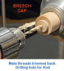
Breech Cap
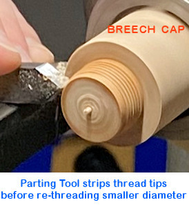 The oversize start permits a thread to be
established and then by trimming the thread tips away, there is enough for the
Chaser to easily engage and re-cut the threads which will eventually reduce the
diameter to fit the female thread in the Breech Bore.
The oversize start permits a thread to be
established and then by trimming the thread tips away, there is enough for the
Chaser to easily engage and re-cut the threads which will eventually reduce the
diameter to fit the female thread in the Breech Bore.
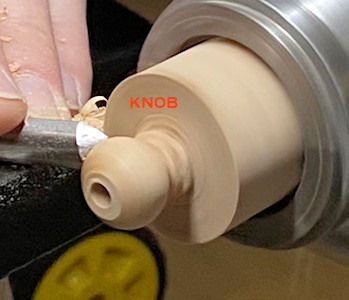
Knob
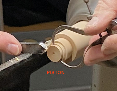
Piston
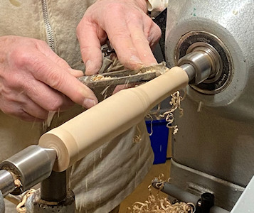
Shaping the Barrel

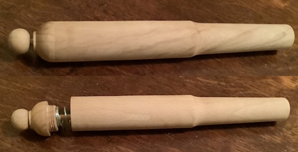
Assembling
Rules for this Competition :-
● The piece will be judged on it's aesthetic appearance;
● It must be capable of propelling the provided pencil;
● The Club will provide 8mm hexagonal pencils with a rubber one end &
blunt the other;
● Powered by Spring/Elastic/Bungee/Compressed Air etc; (Chemical reactions
prohibited!)
● No restriction on size of Shooter.
● The Shoot-Off will be an entirely separate Target Competition from
a table top and its
Rules will be explained on the Night.
The January 2025 Competition was set to create a Pencil Shooter(s) of predominantly turned components that can propel a pencil.
(photos by Andy Ogilvie, Rick
Patrick & Paul Reeves)
<to
index>
Like most musical instruments made for children, the general
consensus is that despite being fun to make, it is wiser to make them for other
people's children and then, only to be presented as they are about to leave your
home!
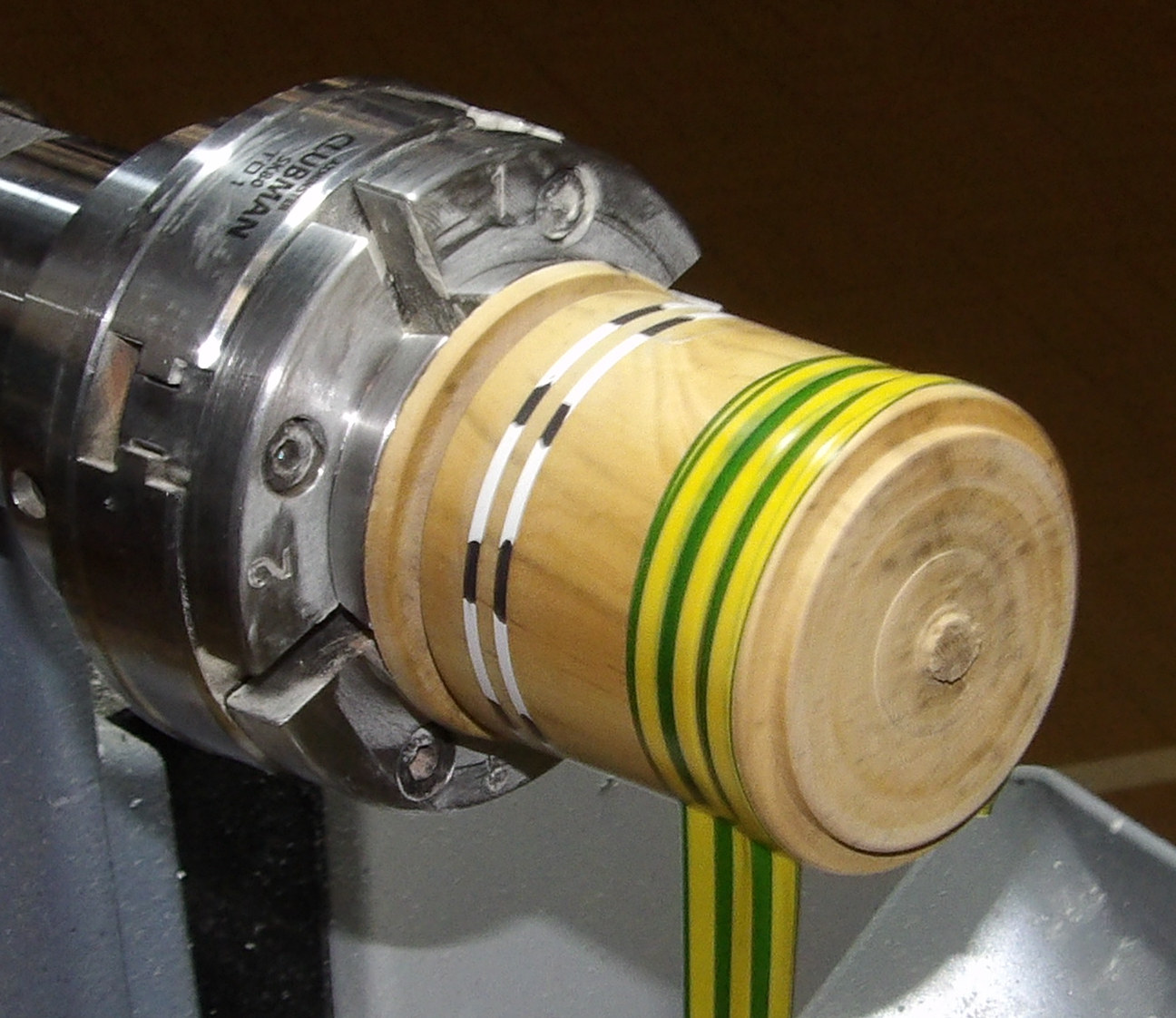
This wooden whistle design is taken from 'Small Woodturning Projects' by Bonnie
Kline of the American Association of Woodturners which is aimed at improving
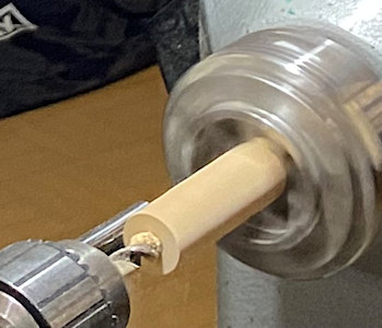
woodturning skills. One needs 2 blanks - one for the Barrel and a smaller piece
to create the 'Windway' from the Mouthpiece to the inner Bore. One could use
prepared wooden dowels although their quality these days are probably not as
good as something you could turn yourself out of a wood to match the Barrel.
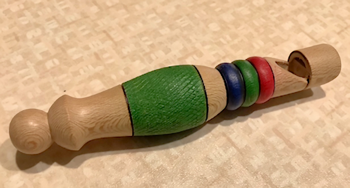
The inside face of the Windway at the Bore end must have a clean & absolutely square edge - the
Exact measurements of length of Mouthpiece, Bore
Notch etc are not critical but a reasonable proportion would have both the first
section (Mouthpiece) and the second (Bore Notch) of about 15mm each. Paul marked
these on the cylinder together with about 10mm for a sphere at the end next to
the tail stock support in order
to gauge a shape for an ogee and any other decorative shapes he wanted in
between.
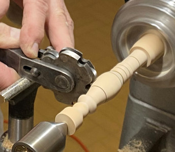
Using a Skew Chisel in combination with a Wire at the planned divisions, he cut
and burnt decorative lines of equal width & colour where marked. He used a 'wriggle' action with his ¼" Parting Tool to reduce cylindrical
areas to required
diameters and
a Spindle Gouge to turn the final shape followed by a quick tickle with
abrasives down to about 240 grit.
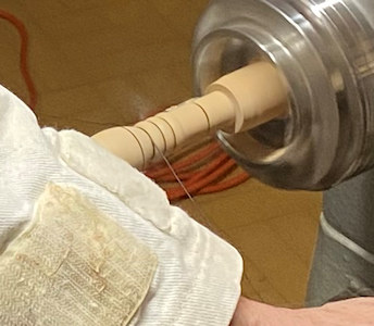
Decoration was applied with a Knurling Tool to produce a light pattern on the
wide part of the Barrel; either a soft brass or stiff bristle brush cleaned the
scurf out of the pattern;
colour pens or stains were applied with lathe set to a low speed in order to avoid
colour bleeding unintentionally into adjacent areas.

The Notch/Slot was cut with a Gentleman's Saw or
something similar with a rigid blade. The first clean crisp cut was
vertically down the whistle from the join mark between the Mouthpiece and Bore
Notch to a depth short of halfway. The next flat cut was angled to meet the down
cut. With the cut-out removed, Paul trimmed with a Chisel to improve the crisp
finish.
The Spindle Gouge finished the spherical end prior to sawing off and light
sanding.
Lastly :
♦ to adapt the spigot to form the Windway.
With it removed from the Friction Drive to expose the previously turned
dowel with its squared off face, Paul rolled up some 180 grit abrasives and took the
opportunity to sand the inside surfaces of the whistle as best he could in order to remove all
remaining 'hairy' bits.
The dowel was trimmed / flattened just prior to glueing in, lining up the flat
with the air hole as the glue went off and then the whole thing parted from the
friction drive. He chose to
sand underneath the Mouthpiece using a round cylinder of abrasives to a shape
resembling a Recorder's mouthpiece.
Once the Whistle was tested and as this was American Plane, he applied a little wax onto the outer
surfaces to seal up all pores in order to deter sweat & dirt stains. If the
whistle had been of Boxwood, Cherry or similar close grain wood, the outer
surfaces would not require waxing.
(photos by Andy Ogilvie, Rick
Patrick & Paul Reeves)
<to
index>
The subject for this meeting refers to a wide
interpretation.
It has been said that
Out of Sheds come Hobby Jobs.
Out of Workshops come Production Work.
but
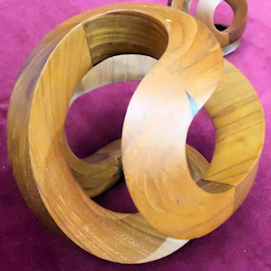
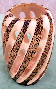
Out of Studios come Gallery Pieces
Turned Wood Sculptures are not straight wood
turned shapes but rather something with a little more thought and intricacies
that are interesting to look at.
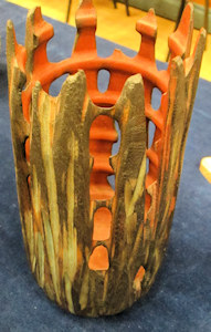
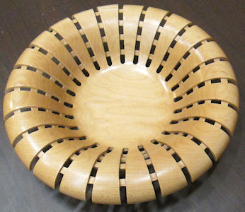
If you are lost for ideas, below are some quality examples of 'Gallery
Pieces' from our very own Members who have exhibited on previous Club Nights (My
apologies that I cannot confidently identify the individuals)

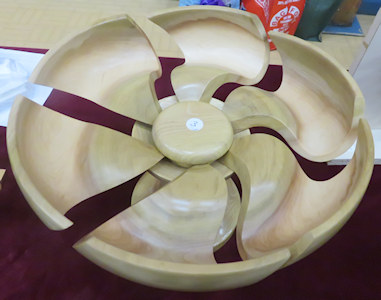
(click this one below for closer view)
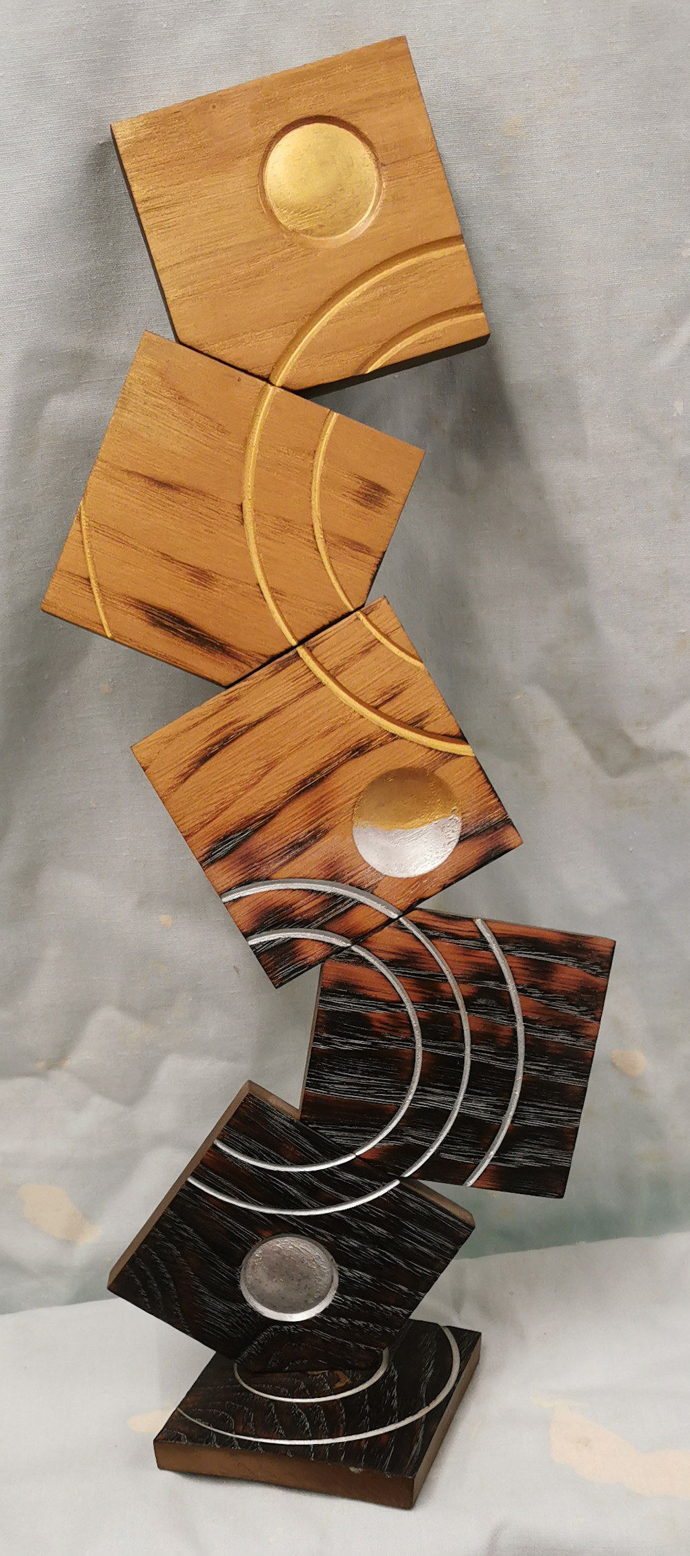
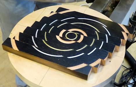
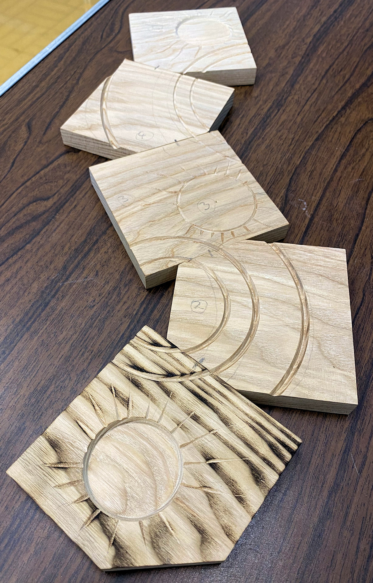
Multiple Centres Turning with Paul Reeves
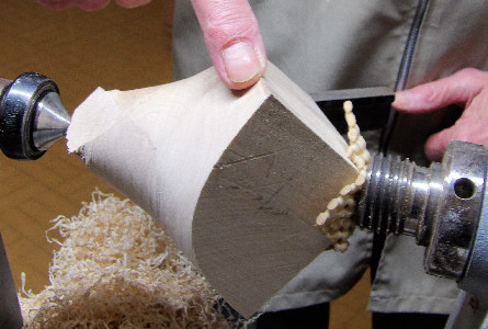
The photo immediately above was for a competition to create something "From a 3 inch Cube" which Paul had band-sawed into six ½" thick squares. He commented that a better starting point would have been a similarly thick quarter-sawn plank (which starts off smoother than any bandsaw cuts) before creating the squares or whatever shapes you decide upon. For this demo, he had spent longer just sanding the 6 squares at home than the entire Club Night time this evening.
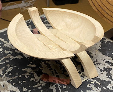
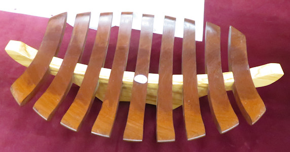
He first decided upon a concept for the
'sculpture' - he chose the theme of 'Night into Day'.
The procedures require the use of a large faceplate which must be very flat,
absolutely square to the turning axis and readily able to take off and replace
back square again. The faceplate needs to be prepared with sanding sealer on
front & back surfaces for double-sided sticky tape to function properly. As some
of the turning will be considerably offset, one might need to stick counter
weights on the back of the plate away from gouge tips.
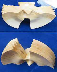
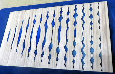
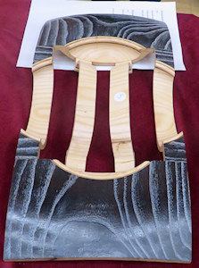
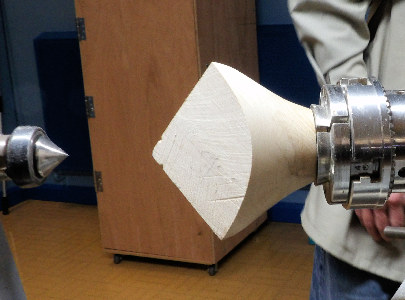
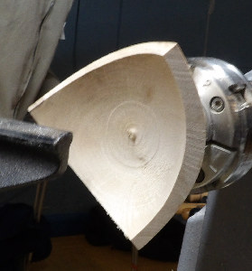
From the photos below, it shows where the frames
were mounted when they were cut. Please note in the Offset photo, the 2
inner arcs were completed first before the Middle & Top frames were removed in
order to complete the outer arc on the Second Down frame. (Top frame had
inadvertently moved prior to photographing).
The Centred photo shows how the Suns & Moon were turned.


(click for closer view)
Only when both faceplate and frame backs were
wiped clean from dust with a Tack Rag, was a frame mounted into the correct
position with at least 2 strips of double-sided sticky tape; 3 strips perhaps
for the far offset frames. Paul used strips running the full length of the
frame's back for a more secure fit.
Paul only used the tailstock to help press the frames onto the faceplate before
it was withdrawn to leave room for working with the toolrest.
The V-shaped grooves were made with a short handle ¼" Spindle Gouge. As
all groove work was intermittent cutting, the gouge had to be moved gently and
carefully to avoid prising the frames off their mountings. It helps to
support the back of the tool to dampen the jarring effect every time the tip
comes into contact with the edge of the frame. Using abrasives afterwards
was not an option so the cuts had to be accurate and each groove of the same
size. Before starting, he had used soft lead pencil marks on the frames to
highlight where the grooved arcs were meant to be as anything paler would
disappear when spinning, particularly those further from the centre.
Paul advised against using a 3 point tool because when applied with intermittent
turning, they tend to barge into the edges of wood rather than a gouge slicing
the wood away.
The Moon & 2 Suns were individually mounted dead centre and their edges were cut
out with the gouge. They were finished off as an indented dome shape with
identical diameters (remember a total eclipse has the moon marginally larger
when viewed from Earth). When removed from the faceplate, they were further
decorated with 'rays' by using a powered Proxxon Veining Chisel. Paul considered
Sun rays should be conveyed with wavy beams while Moonbeams should be straight.
Once satisfied, he re-trimmed the outer edges of the heavenly bodies.
Next was scorching in the 'night' frames. Rather than using his heavy duty plumbers torch, Paul had found the Draper Gas Torch (running off gas lighter fuel) perfect for tidy controlled burning. This was followed by cleaning up and painting in the grooves - silver for the moonlit frames and gold for the sunny ones. Finally, the frames were attached together with Panel Pins as studs and with glue.
(photos by Andy Ogilvie, Rick
Patrick & Paul Reeves)
<to
index>
Jewellery is worn for several reasons. Whether
personal or functional, it should be comfortable while avoiding being heavy or
rough to wear! A small item or groups of small items are consequently
ideal, but in order to be distinctive when small, one needs to either select wood that
is more
striking than ordinary, or else a plain wood that can be made interesting by
decorating with texture, coloured waxes or resins filling indents etc.
Sometimes, off cuts from previous projects can be a good source but be wary of
loose grain wood which will lack sturdiness and liable to break up when thinned.
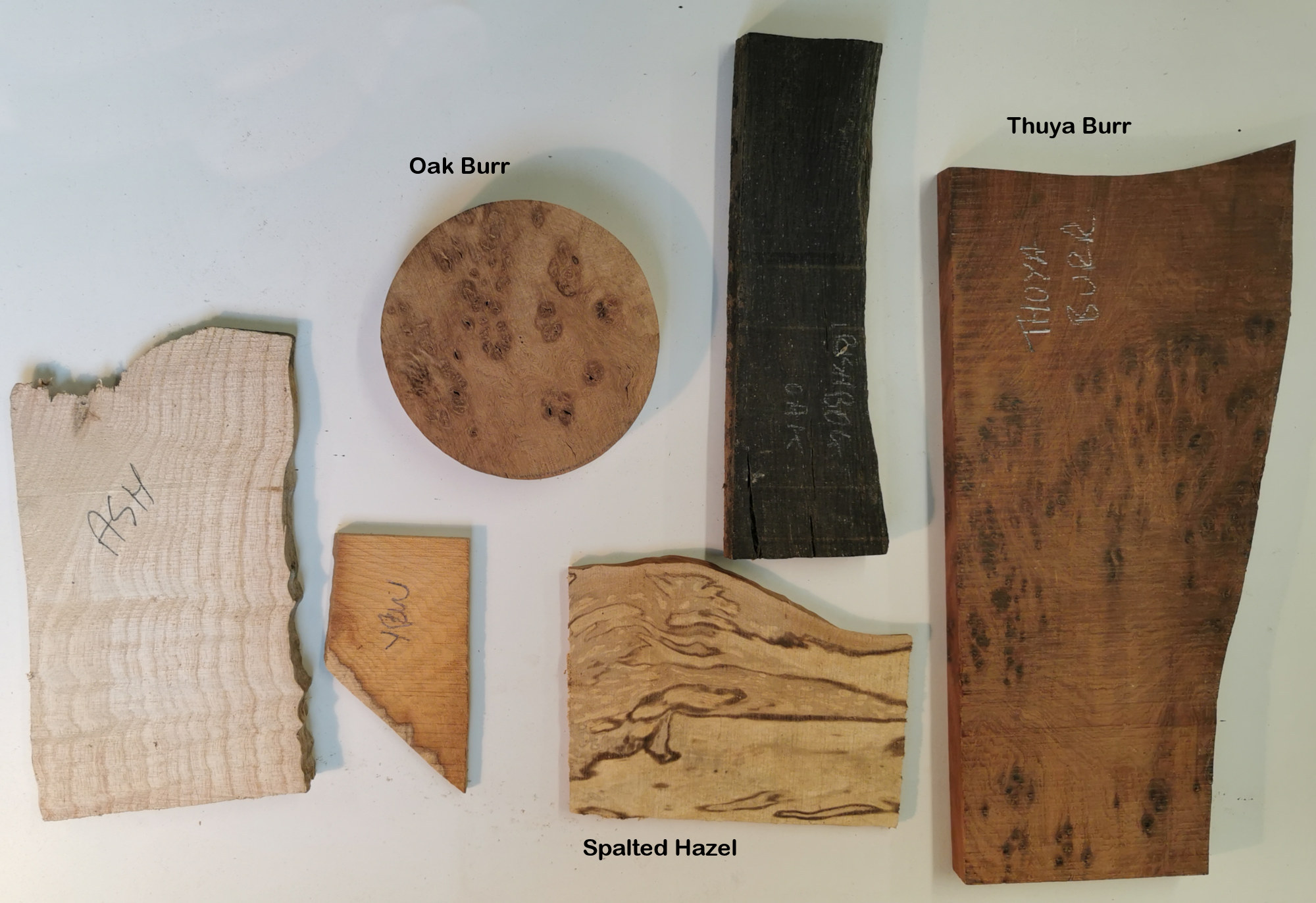
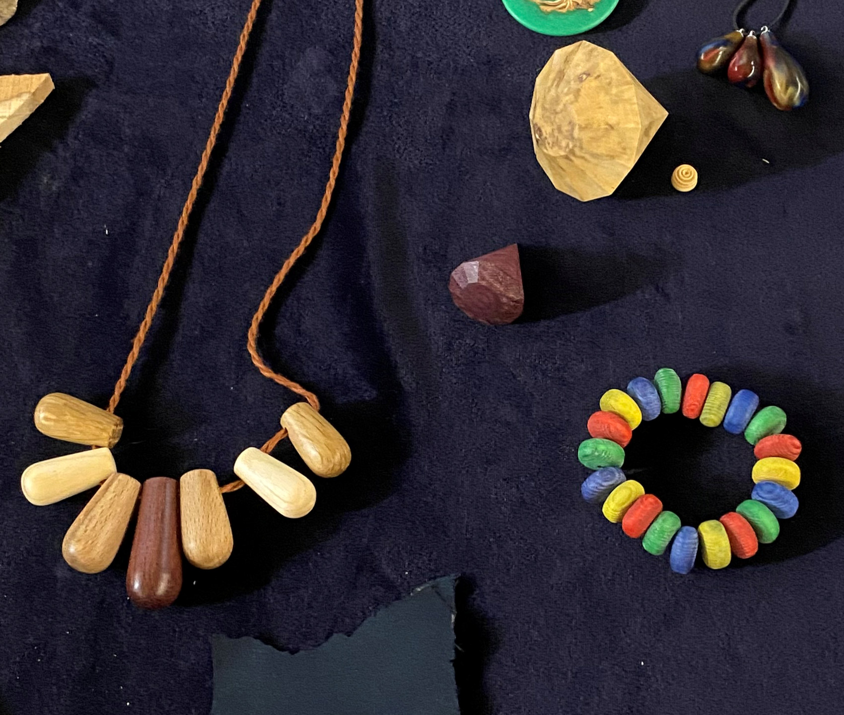
Below are some suggestions of what to keep an eye
out for.
(click for close up view)
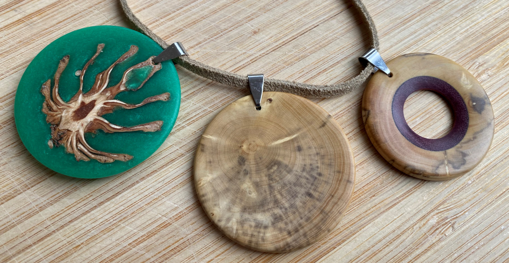
And below are some examples of jewellery turned on a lathe :
(most of below can be clicked for close up view)
At home, Andy had used a set of Pen
Jaws which gave more distance / leeway for knuckles not to be rapped whilst
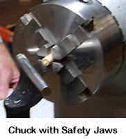
doing close work, whereas at the demo, he only had External Safety Jaws which
gave problems of limiting the techniques available and also left slight witness
marks from the jaws' tight hold of the previous work. The use of Pen Jaws (with
their round insides) minimised these marks as well as reduced the chance of
drawing blood!
A good alternative chucking solution might have been a Collet Chuck.
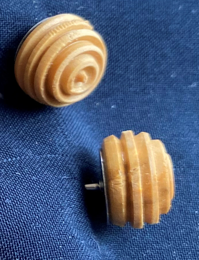
A
spindle square blank of Boxwood had been turned to an approximate 12mm dowel.
Having mounted the dowel as suggested in his tip above, Andy used a Skew to trim
the dowel side true before clean cutting across the protruding end. He
used the Skew edge to scrape off the corner of the end face to about 45º but
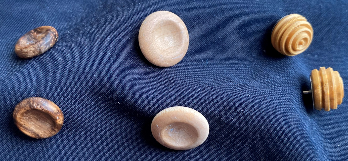
left the end face with a 3mm/4mm flat circle. Using the Skew again, he scraped the 2 new
corners he had just produced which left the dowel end approximately
hemispherical. He marked the piece about 9mm from the end to where the
earring would eventually be parted off. He sanded the piece with some 240 grit
abrasive while he still had a smooth shape to work because his next cuts (with a
small 3-pointed tool) created a circular cove around the end and a further 4
similar depth coves about every 30º around the shape, which would make it impossible to
obtain a smooth flat surface without spoiling the coves' edges. He used
the side of his 3-point tool for the last shape to the part off mark to suggest
a continuation of the sphere shape. He parted off ensuring the base was at least
8mm diameter to accommodate the Stud Post after sanding the base flat to receive
it. It just remained to repeat the process and superglue the Stud Findings onto
their bases.
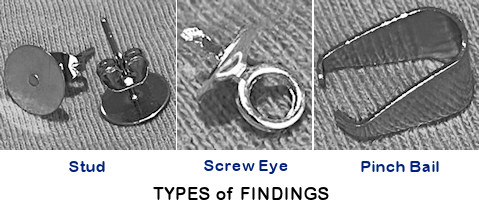
NB : 'Findings' is the general term used for jewellery fixings.
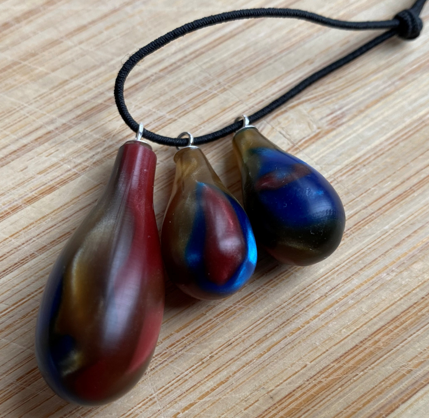
Necklace
 To
highlight other ideas,
Andy had examples of Pendants & Bracelets (photos above) with contrasting wood
combinations and a pine cone enveloped with resin and turned thin.
To
highlight other ideas,
Andy had examples of Pendants & Bracelets (photos above) with contrasting wood
combinations and a pine cone enveloped with resin and turned thin.Andy also suggested that 'findings' including Screw Eyes and Pinch Bails could be obtained by typing something like "Jewellery Findings" into your browser to generate plenty of options from the likes of eBay, Temu, Amazon etc although anything silver does tend to be expensive.
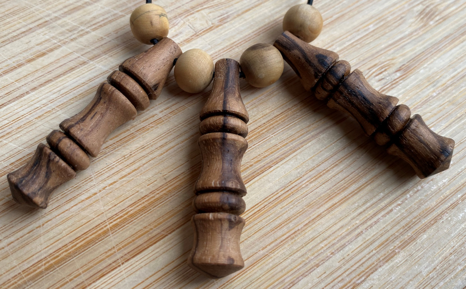
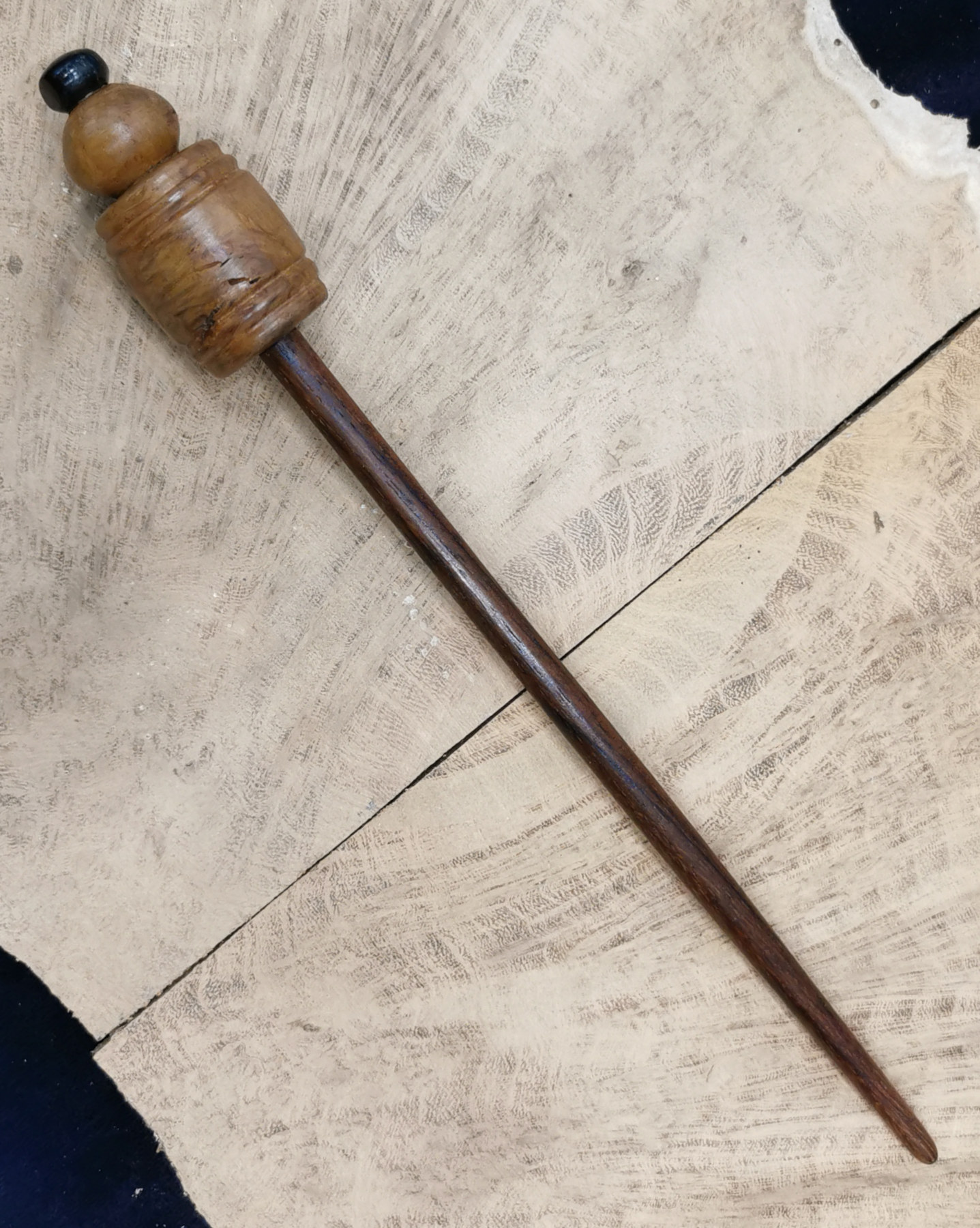
Paul displayed a few examples of his own made
jewellery including 3 Lollypop Hair Pins made of Rosewood stem with Oak hand piece plus Irish Bog Oak as dark
pin head; some blanks for Silk Scarf Rings; Bangles (70mm minimum for getting
over a lady's hand); a burr toggled Pendant (which he knows better as 'Greta's
Badge of Office') and a Pink Ivory Ring.
He pointed out that any burrs within Jewellery must NOT have any sharp edges
left on the piece but can be removed by filling in
with wood dust and superglue to smooth them over.
(click for close up view)
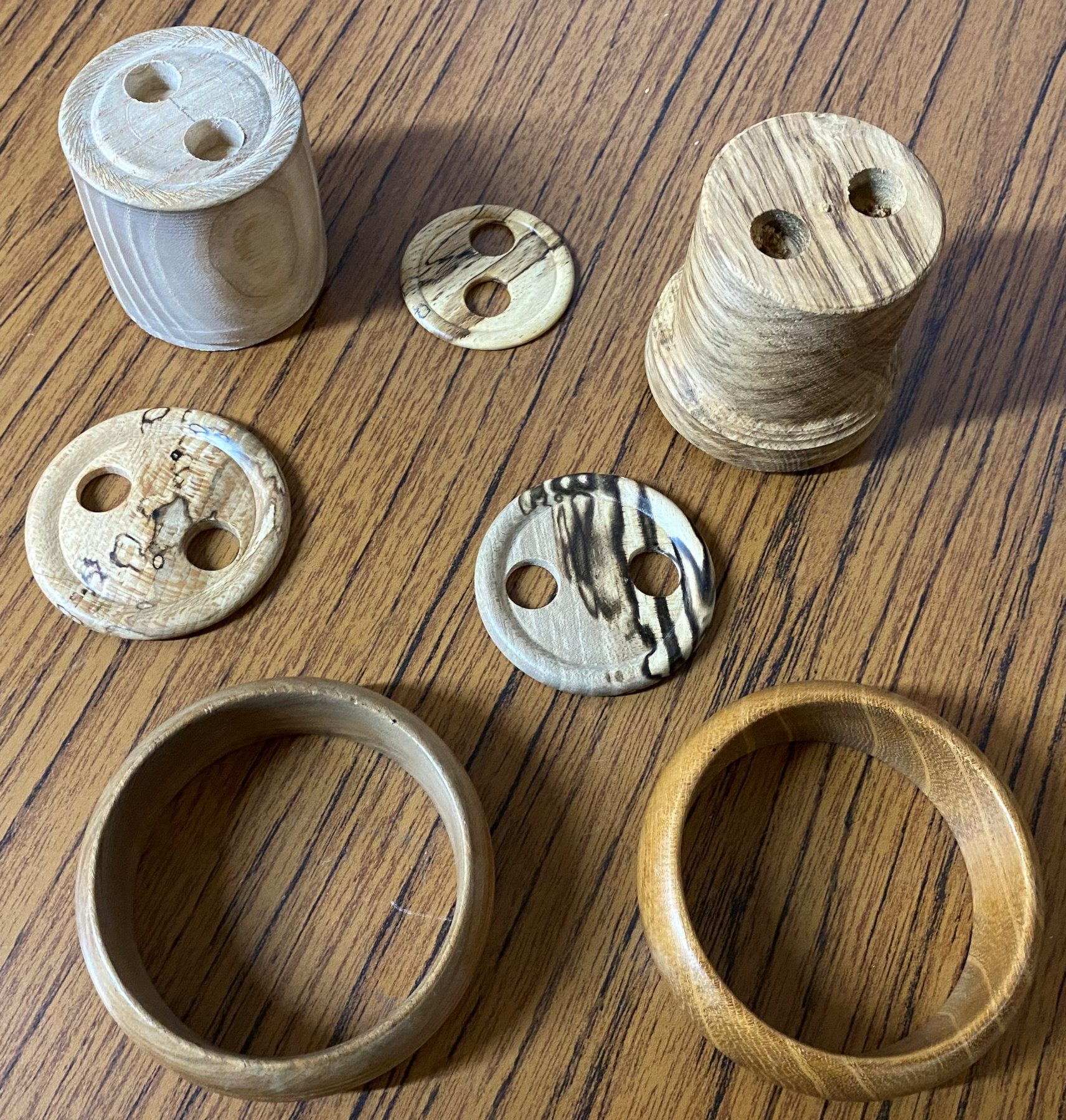


Silk Scarf Ring
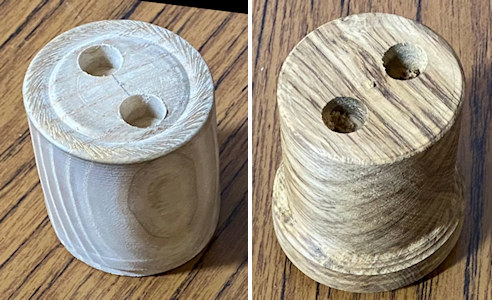
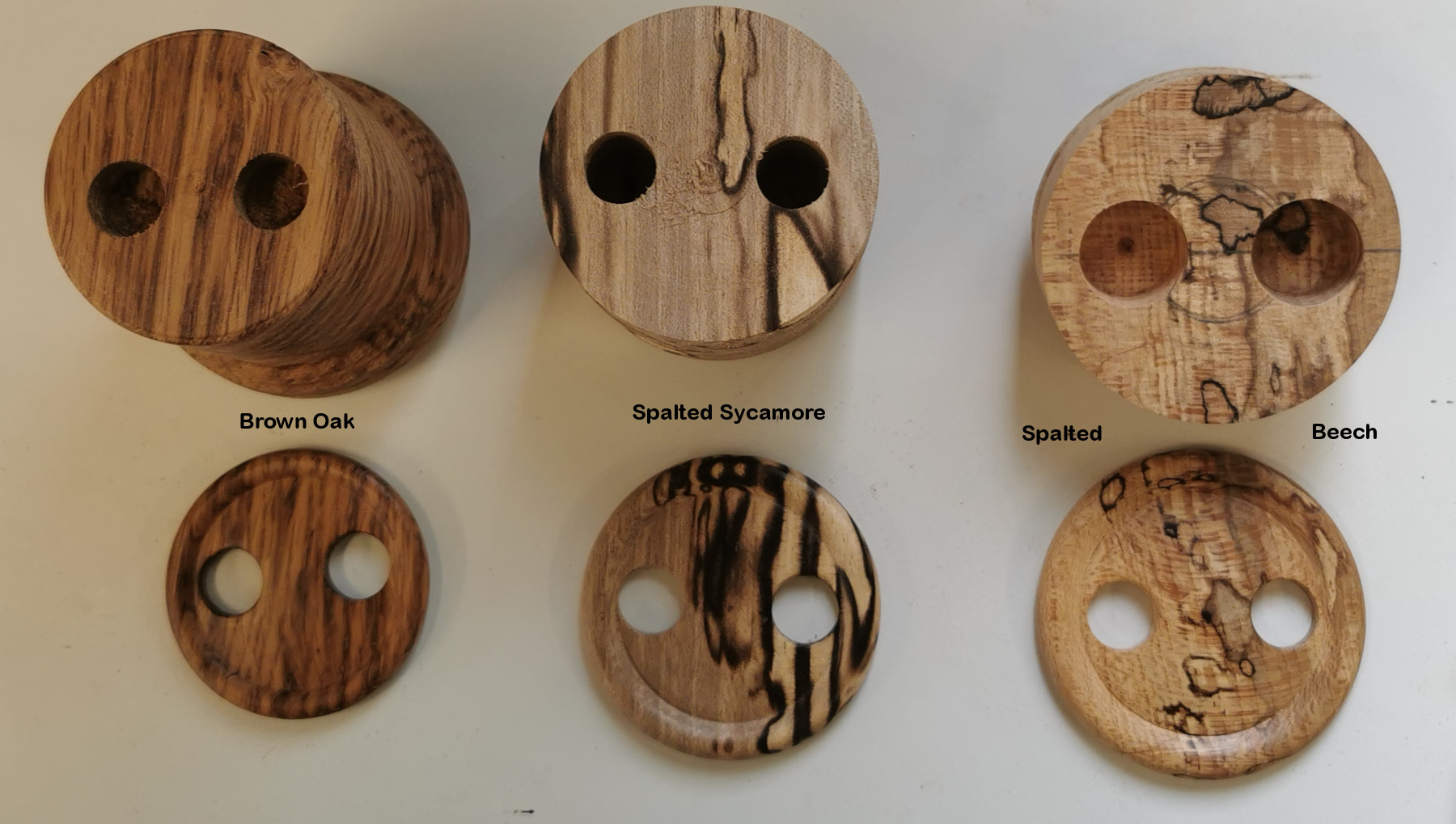
Bowl Squares were bandsawed or
gouge-turned
into cylinders of 50mm to 60mm diameter. The blocks had been prepared with 12mm holes with at least 10mm
clear between their adjacent edges. Paul had found that twist drills tended to rip the
edges upwards so he used his sawtooth drill bit to produce clean even holes.
When a silk scarf is of colourful or intricate design, one might prefer the ring to
be plainer so as to not compete with the beauty of the silk. Perhaps like
the pale wood above, which has its outer rim decorated with an Elf and gold gilt
cream to make it 'interesting'. When the scarf is just a single colour,
then a more striking wood might be appropriate.
Whichever is chosen, when the scarf is in position, it will cover up virtually
all of the centre of the ring.
This demonstration was with a block of Brown Oak. It had been pre-drilled with
two 12mm holes so the first job was to smooth and shape the front face with a
small ¼" Spindle Gouge. Because of having to cut with those holes coaxing a
gouge tip to drop in and cut the oncoming hole's edge, it is important to avoid
having a heavy push of the gouge onto the wood but instead have a firm hand
controlling the gouge on the toolrest with just a gentle pressure onto the wood
while moving towards the left. This control is helped with increased lathe
speed. Paul planned to smooth the centre and to take more wood out towards the
edge while leaving a raised rim edge. This was achieved by starting off
with the gouge cutting with its tip and left wing at the centre of the piece but finishing by rolling the
gouge so that only the central tip was cutting at the moment it reached the edge
of the rim. This required a lot of hand movement; the gouge tip might have moved
1cm while the handle had moved 4cm while tip and handle both had to keep moving in
the same direction. The right hand has to catch up the left by moving in a
longer arc.
One could also use a Skew/Scraper in the same fashion as Andy had done with his
pegs above.
With the lathe speed slowed and the toolrest moved out of the way, Paul set
about sanding a ring with 2 holes. With the lathe turning, one must not hold
abrasive with an edge facing upwards into a down coming hole. So if the
lathe is turning, hold
the abrasive in your fingers so that it hangs on the same side as the rotation
direction. If you didn't, the loose abrasive edge would snag in the holes.
Bear in mind if you reverse lathe
direction or you choose to sand from the other side of the rails, you will need to reconfigure the abrasive in your hand.
Ideally, doing your tool work well reduces the time needed for sanding with your
lathe turning. Paul finished off sanding with the lathe stopped and used 240
grit to gently round off the edges of the holes to ensure the silk wouldn't snag
on any roughness.
Finally, a thought had to be given as to how thick does one part off. Too
thin risks the ring snapping in half; too thick risks its own weight will
overcome the friction of the two silk corners going through the holes and fall
off. Paul used a thin Parting Tool, which seemed contrary to select when
it's designed purpose is to cut across single grain direction of spindle wood.
However, provided the tip is very sharp, this tool does a good job of getting a
smooth and flat back face with little further sanding.
With Brown Oak being quite tight grained and dense, Paul parted so that the ring
thickness was about 5mm. He made the cut wider than the width of the tool
so that the final parting cut was away from the back face in order to avoid any
grain pull-out in the piece.
Pendants
The bottom line with this example is that most people hold their blanks too
firmly which is unnecessary so long as you are careful with your tooling. For
example, if working on the back face without checking the pendant is steady in
its setting, a heavy hand on your gouge could press one side in, which might
flick the other side away from the sticky tape and spoil the whole cut. Once it
was cut gently & smoothly, Paul chose to decorate the back with a couple of
concentric circles, just because he could.
When it came to sanding, Paul had carefully tooled some detail on both sides and
aware that those crisp edges would be quickly removed by abrasives, he opted to
carefully tidy the surfaces with 320 grit and finish with a bit of wax and a
Pinch Bail Findings to connect to its cord.
The November 2024 Competition was set to turn attractive piece(s) that can be worn for personal adornment
(photos by Andy Ogilvie, Rick
Patrick & Paul Reeves)
<to
index>
August 2024 DEMO
3
Straight
from
Tool turned pieces with
 Paul
Reeves
Paul
Reeves
Thu 15th August at MWCC Club Night
Straight from the Tool is a technique that
provides the best possible turned surface without requiring any use of
abrasives. To perfect this, takes time & skill.
Indeed, it wasn't until the 13th century before sandpaper was
invented in China and before then, any wood turning had to be left as tool
finished with the possible exception of refinement using wood shavings and (in a few parts of the
globe) fish skins.
Trying to complete a turned piece "straight from
the tool" shows up one's Tool Control, Tool Sharpness & Lathe's performance in
absolute clarity.
Control relies upon practice & experience of getting the bevel
position correct;
Sharpness comes with recognizing when a cutting edge needs attention;
Performance deteriorates from adverse vibrations caused by worn bearings of
headstock drive centres and/or tailstock centres or even a lumpy toolrest while
moving one's gouge along it.
Some turners have no alternative to turning this way - for example,
the fascination of Pole
Lathe turning is the hand-made look of natural tool finish;
Ornamental Lathe
turning relies upon intricate sharp-edged decorated pieces that would be ruined
by sanding.
How many of us take time to just practice using our gouges to achieve a smooth
finish, particularly with a 'difficult' wood to work, eg Paraná Pine? You
will quickly discover
that you need to select the right wood for the project,
that sharp tool edges are essential and
that high lathe speed is often your friend.
Spindle Work
Along Grain :
Paul had a piece of Paraná Pine mounted between centres and knocked the corners
off with a Roughing Gouge presented at right angles in the first instance to produce a
cylinder with a dull finished surface. This surface was improved by
presenting the same gouge angled at about 45º from vertical with the bevel
smoothing off the freshly cut surface as it moved along the tool rest. An even
better finish is with a Skew Chisel achieved by raising the toolrest so that
only the lower third of the tool is in contact with the upper quadrant of the
piece, which avoided adverse twisting of the tool in your hand and sliding
off the rest. The German Christmas Decoration turners of Seiffen use a square
ended tool but angled Skews are invariably used by us. These Skews have cutting
edges angled either straight or curved in an arc. The curved type have the
advantage of finer control by easily adjusting the cutting point by up/down
movements of the handle but the more acute the angled edge cuts the surface, the
more difficult it is to stop the cut moving in/out creating ripples so it does
demand very steady hand movements. The straight angled Skew is more stable for
the occasional Skew user.
Top Tip
: if using
any angled Skew, use the edge with the shorter side resting on the toolrest - or
in other words, with the acute angled corner uppermost. Move with your
body rocking on your legs rather than moving hands with your arms.
The Skew finish can look and feel like you've sanded down to 800 grit and
frankly, any use of abrasive is likely to be detrimental.
Cross Grain : Paul demonstrated different tools one could use.
①
His ¼" Beading & Parting Tool was shocking at cutting across grain causing
multiple pull-outs;
② His thin tipped Parting Tool
had less contact damage which was fine with close grain woods;
③ His Skew had the best finish
provided he only cut tiny slithers (about ¼mm)
successively but this time with the longer side resting on the toolrest (i.e. sharper
angled corner lowermost).
(click for close up view)
Beads and Coves are also cutting across the grain of spindle work and require a recently sharpened Spindle Gouge to cut from larger diameter to smaller. These procedures were previously described back in May 2024 and can be found in 'Spindle Revision' < here >
(click for close up view)
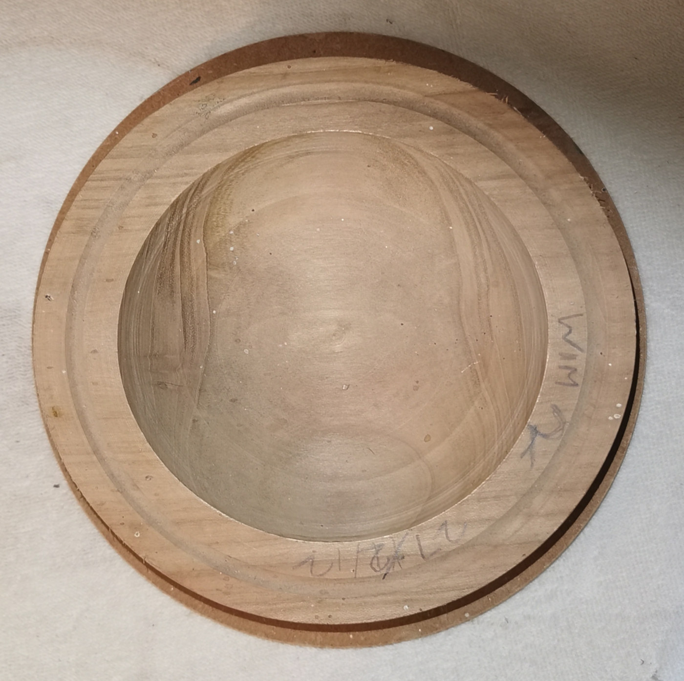
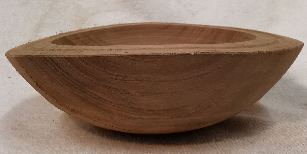
Bowl Work
As the walls of a bowl comprise of a
combination of along/side grain and across/end grain wood, fresh cut blanks will distort
as they dry out.
It is essential for the dried blank to be held solidly in your chuck jaws when
you are ready to finish it, so some thought should be put into how to rough your
bowl in preparation.
Bowl blanks are best roughed out to a wall thickness about 10% of the overall diameter as this is
average shrinkage amount around the annual rings and leaves plenty of room to
true up later. Some woods eg Alder, Yew hardly move at all whereas Cherry (as
you can see from the picture below) moves a lot during shrinkage when the wood
also warps in two directions; i.e. the opposite sides
that are along grain will shrink closer together and to a lower height than the
across grain sides.
(click for close up view)
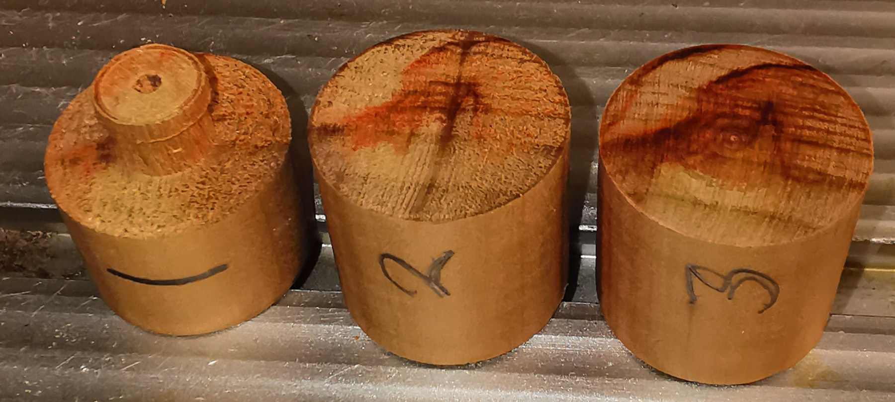
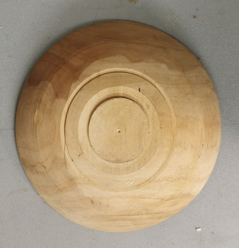
Paul anticipates this by roughing the blank so that the spigot on the bottom is
finished with a pop mark in its centre and pencils the date on the bowl's lip.
If the roughed out bowl is either wide or shallow enough for a chuck key to
operate, he additionally creates a dovetail spigot inside the bowl bottom
together with a pop mark there too. Note
that some chuck keys have hexagonal ball ends that can still adjust the jaws at
oblique angles.
Once dried out many months later, the outside
spigot will be oval and will need to be re-trimmed circular, ideally to the
'True Circle' jaw diameter in order to be held rigid even if the spigot is only
a few millimetres proud.
This can be achieved by :-
either driving the piece between a Jam Chuck acting against the inside of
the bowl and a tailstock centre pressing into the pop mark,
or if applicable, with a chuck gripping the prepared inside dovetail and with a tailstock on
the pop mark.
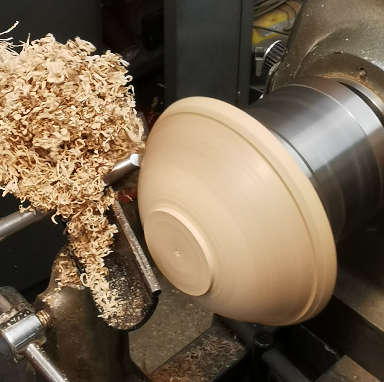
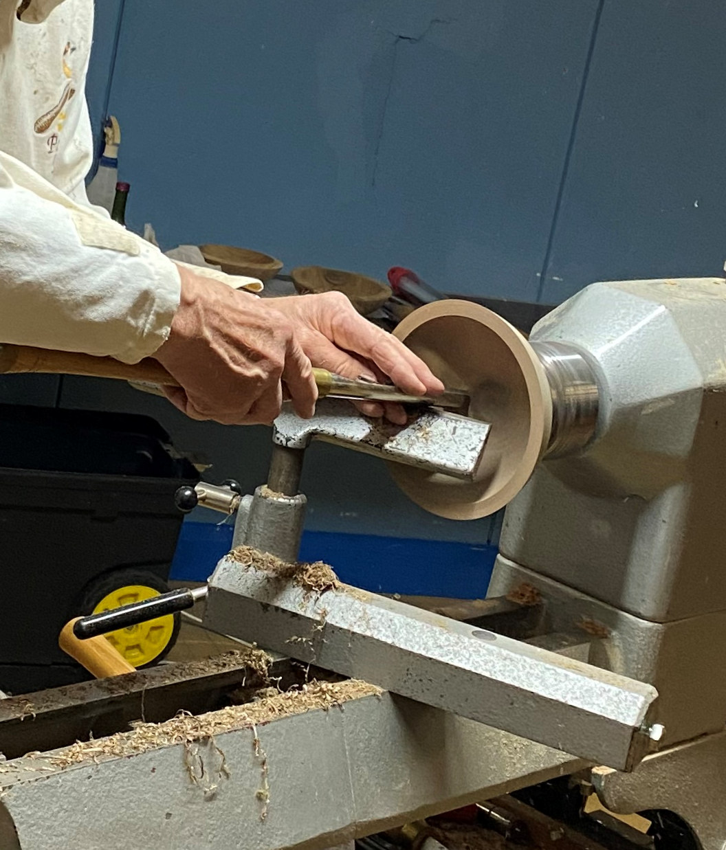
Outer Surface
Paul's Walnut rough blank did have an internal dovetail - but first, he gripped
the outside oval spigot as best he could with the inside supported by the tail
stock in order to level off the lip of the bowl.
Then with the piece remounted with long-reach or o'Donnell jaws to the inside
dovetail together with a tailstock to the base pop mark, he re-trimmed the base
spigot to true circle as described above.
(click for close up view)
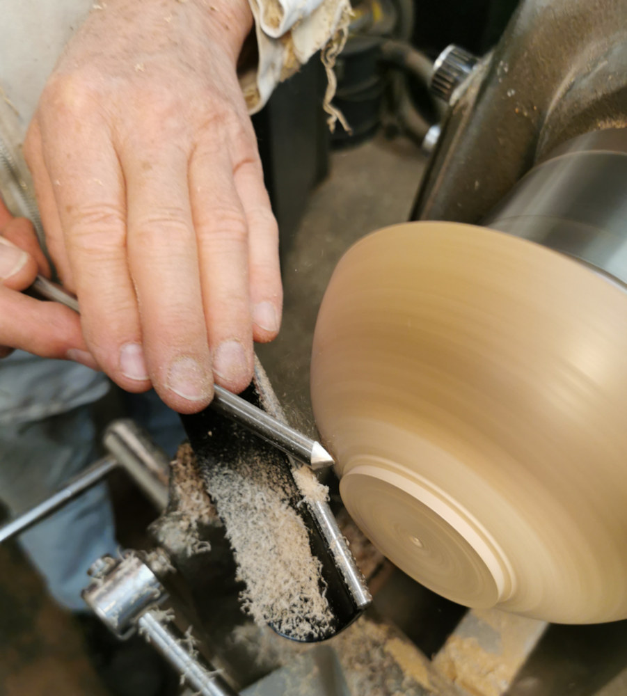
While mounted in this position, he applied pull cuts from the centre to about
halfway up the side; if he had continued any further, he would be dragging the
tip over wood that was rapidly changing from side grain to end grain twice every
revolution, which would end up rough - particularly with hard dried out wood.
In order to give a better surface cut, one can change the pull into a push cut
by moving the tool handle from in front of to behind the tip in one deft
manoeuvre such that the bevel will now smooth the cut onwards to the lip of the
bowl.
Unfortunately, this Walnut bowl was so hard in places that it was difficult for
Paul's gouge not to be kicked about uncontrollably. There were 3 likely
explanations :-
1. Combination of the lathe speed & the gouge were moving too quickly;
2. Pushing too hard down on the gouge;
3. Cutting tip was above centre and the hard parts of the grain were
ending up bouncing against the bevel resulting in only the softer wood getting
cut away leaving the hard pieces getting relatively higher, aggravating the
fault.
Incidentally, if one resorted to abrasives at this stage, it would compound the
situation because more would be lost off the softer along/side grain than the
denser across/end grain resulting in a change of bowl shape. In Paul's
Walnut bowl piece, this was further accentuated as the sides were sapwood and
the ends were heartwood.
The solution is to carefully cut away the hard parts in tiny amounts on each
pass. All other methods (e.g. scrapers) are likely to result in pull outs.
Sharpening
your gouge or changing to a smaller tipped gouge can help.
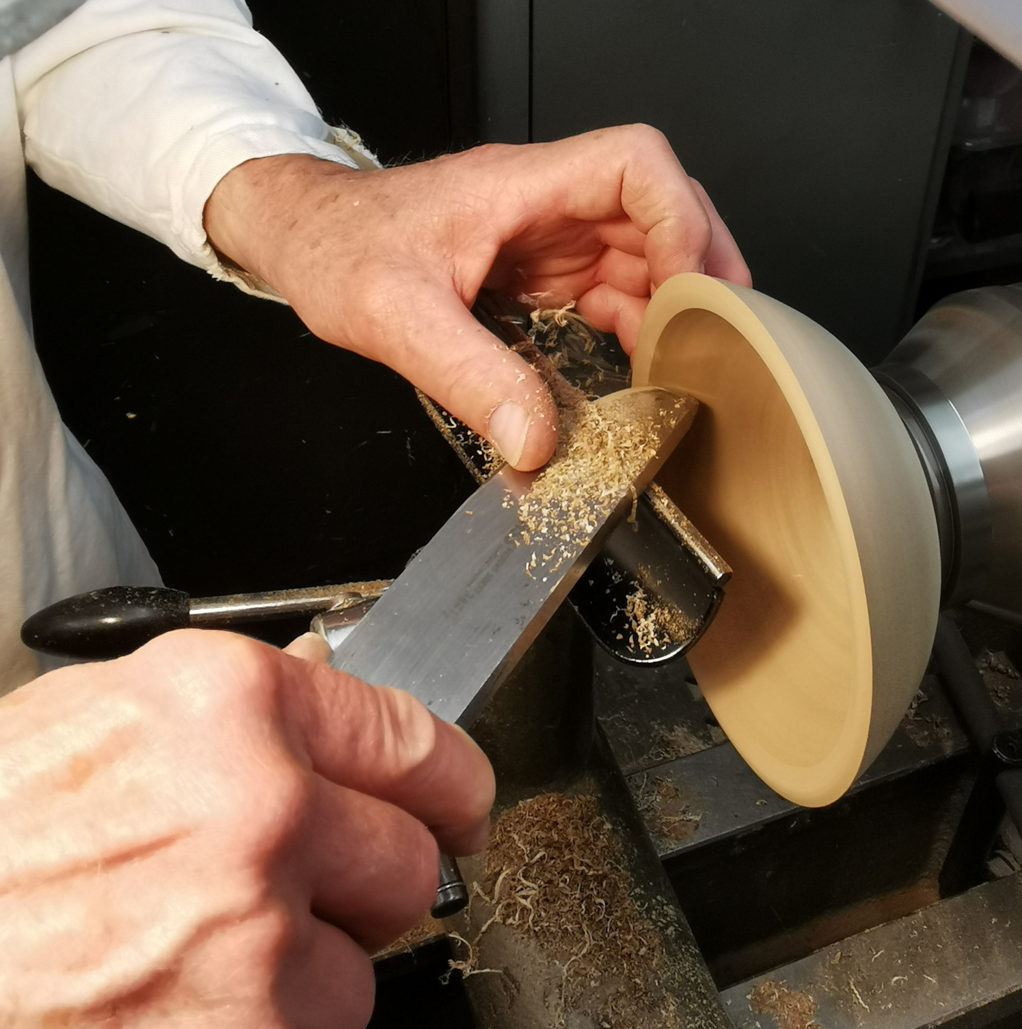
To remove tool marks, a useful ploy is to use the lower wing of a Bowl Gouge to
gently dress the surface with a slight shearing angle. Be careful to
ensure the top wing does not touch the piece with this method. Many
of us sharpen gouges with a 'fingernail' profile whereas a straight edge wing
profile is better for this job.
(click for close up view)
Sanding Sealer (quite acceptable for tool finish pieces) will help to stand up
the wood fibres making it easier to cut them off.
Top Tip
: Although the wood fibres are now standing proud, they are all
still bent over in one direction. If your lathe is capable, when getting to your
finishing cut, try reversing the direction of turn and with the tool rest and
gouge/shear scraper positioned to the far side, you will now be cutting from
underneath the raised fibres, resulting in a much smoother finish. This is the
same reason that changing direction of turn with abrasives is so effective.
This will work for both inside & outside surfaces. NB Beware that heavy
contact could start to unscrew the chuck from the head stock.
After applying Sanding Sealer with brush or
cloth, pressing paper with lathe turning created heat to help dry the sealer
off. Now when you pass your gouge over the piece, wherever the surface is low,
the untouched Sealer shows up as still shiny.
One also needs to consider whether the surface you are working will be in
contact with food, in which case use water instead of Sanding Sealer to stand
the fibres up.
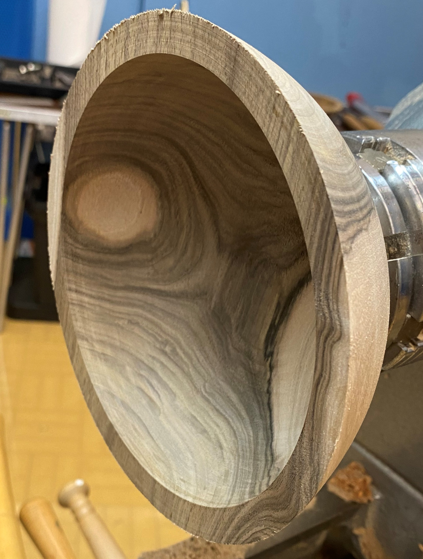
Inner Surface
With the piece remounted on the base spigot, Paul
quickly removed the inside spigot in order to be able to make one continuous
pass for the following cuts. Whenever one stops a cut and restarts again,
it is inevitable that a witness line will be left on the surface.
One remedy is to use a curved surface tool. Although it is better to cut
rather than scrape, smooth movements, for example, with a Negative Rake Scraper
can provide the finest surface finish. However, the drawback is the edge doesn't
last very long and needs regular tickling with the diamond file whenever the
shavings become irregular. Reapplying Sanding Sealer often helps when you are
near the final passes.
The correct use of a scraper is to position the toolrest so that the tool is
slightly handle high with the cutting edge at the 9 o'clock position. If your
Scraper (e.g. Taylor Teardrop Cutter) has a round bar sitting on the tool rest,
one can avoid the tendency of the end grain parts of the piece from being
levered up by twisting the tool anticlockwise such that the scraper edge is at
an angle, which will help to slice the surface.
(click for close up view)
Now it is just patience and care to
remove all the tool marks as best that you can by trying to reach the same
colour without the Sanding Sealer highlighting any lows.
Paul finished with shaping the rim and its inside edge with his Negative Rake
Scraper while carefully supporting the outside surface with his fingertips.
(click for close up view)
The September 2024 Competition was set to turn piece(s) without any sanding - although oil/sealer finishes are acceptable
(photos by Rick
Patrick & Andy Ogilvie)
<to
index>
June 2024
DEMO 2
Mixed Solid Media with
 Andy
Ogilvie
Andy
Ogilvie
Thu 20th June at MWCC Club Night
SOLID MEDIA refers to different materials that
can be worked.
These include :
wood
soft metal
epoxy resin
acrylic
Perspex
Corian
Milliput epoxy putty
etc
A piece of wood with just paint, pyrography or made out of 2 or more different types of wood doesn't
strictly satisfy the
criteria of
MIXED SOLID MEDIA,
whereas, two or more combinations of the above examples does, whether used within the
body of the piece, or as a decoration.
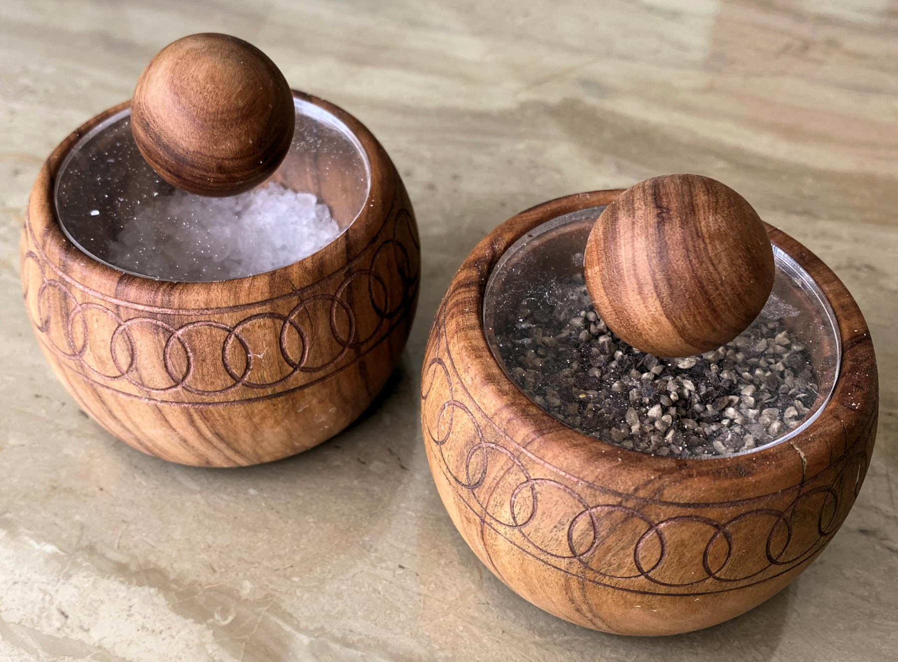
For example, Andy had used
Perspex as a lid to his wooden kitchen Salt Pot to
keep moisture out while able to see what was in that particular pot;
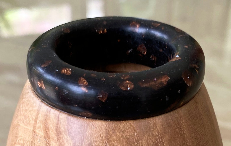
turned
Corian to enhance an opening;
napkin rings decorated with Milliput;
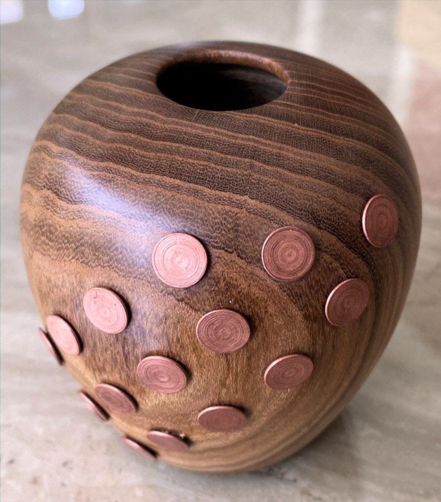
a Laburnum
urn decorated with brass rivets.
(click for close up view)
(click for close up view)
In précis, Mixed Solid Media pieces
can be :-
♦ COMBINATIONS of the above media or kits (egg timers, clocks, pens etc);
♦ DECORATIONS of solid media applied to a piece;
♦ INTEGRATED MATERIALS which form a blank for subsequent turning.
This demonstration will give more
detail of how to achieve some of the above processes.
Andy warned that using open-grained wood had difficulty in maintaining a sharp
edge between wood and putty/metal alloy once the piece had been sanded back to a
smooth finish, because the slurry had a tendency to penetrate into the wood
grain resulting in a cloudy grey effect near the joint between the media.
For his demonstration, he had chosen Boxwood.
Andy's basic message was, "Don't be put off with experimenting with these
various materials just because they are unfamiliar. They are all manageable."
Milliput Epoxy Putty
Milliput comes in 2-pack blocks of putty in black, yellow grey, silver grey,
terracotta and superfine white, (the latter can be used for creating very fine
details). In preparation for applying his Milliput around the body of his
box, Andy used a Parting Tool to create a recess about 3-4mm deep and about 5mm
wide, although he deliberately countersunk the sides to be wider at the bottom
of the recess in order to help secure the putty in position once cured. After
cleaning the surfaces, he applied a coat of sanding sealer which would help
keeping the wood clean with a simple wipe.
When new, the putty is malleable
although it will be less so with age after opening.
Top Tip
: If putty has become stiff
with age, try working each block separately while under the stream of warm air
from a hairdryer but be aware that heating reduces the curing time and hence
less time to manoeuvre into situ. Adding a
little water can also soften the paste.

Having selected equal quantities of both parts, Andy mixed them well together before rolling out into a thin sausage and pressed into the recess while aiming to minimise gaps/holes. There was no need to skimp on the amount used because it cleans off easily and used for the next recess. Andy often uses different width of recesses to create interest.
Depending upon temperature and age of putty, it would take about 2 - 3 hours for the Milliput to 'cook' and harden off enough before one could turn the piece with a gouge or sand back. Milliput can be readily shaped by gouge and particularly receptive to sanding.
Andy also described other effects that could be produced using different coloured putty like the black and white chequered feature shown below.
Soft Metal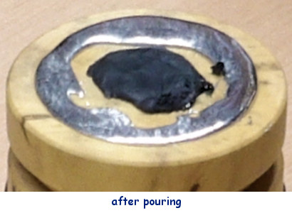
Andy had brought along some "Wood's Metal" bars of bismuth/lead/tin/cadmium alloy which have a
surprising low melting temperature of 70ºC (not much hotter than solder) and
would melt in a spoon with a hot air gun, particularly when the
alloy bar is cut into tiny pieces. He warned against using solder as it
tended to be difficult to pour without solidifying before it filled up all the
space and it doesn't polish up as well as the alloy. Pewter is a suitable
alternative but requires higher temperature to become molten.
As we are relying upon gravity to help us, trying to cast a metal ring around
the side of the box is a difficult process. However, flat surfaces like a box
lid are perfect.
So while the lid section of his box was still connected to its body on the
lathe, he prepared as he had done for the putty by forming a countersunk recess into the end of the piece but then added a slight bevel to
the edges of the recess; these bevels encourage the molten alloy to fall into
the recess.
After cleaning the surfaces, he again treated with a coat of sanding sealer.
With the lid now set flat, the chips of alloy were placed in a spoon and heated with a hot air gun until molten about 45 seconds later when it was poured into the recess. Enough alloy was dropped in for the meniscus to just bulge above the prepared bevel. This was to allow for any dipping as the alloy cooled & solidified. Dependent upon the volume of alloy used, it should be ready to work within 10 to 30 minutes. The aim was to minimise wastage and to have very little to turn away with a gouge. Before any sanding, another coat of sanding sealer was applied and subsequent abrasives were carefully used lightly with fine grits only & at a slow speed to avoid frictional heat re-melting the alloy.
Integrated Resin
A quick Google search for "resin for beginners kit" will show there are many
suppliers out there, which might seem daunting but can be rewarding with a
little perseverance. There are 3 types of resin; Epoxy, Polyester &
Polyurethane but epoxy is best for gaining experience. Many starting sets
are for thin projects but woodturning
projects tend to require several centimetres thickness, which you will need to
consider before buying.
They all require mixing of the resin with a hardener. The deeper the
cure mixture, the more that stirring and higher curing temperature can create
bubbles which would detract from the finished article. To overcome this problem,
some suppliers sell specific epoxies & hardeners for different depths while some
guide you to different ratios of resin to hardener. Others explain how to remove
bubbles using heat guns or even toothpicks! One method includes using
pressure pots that will compress air bubbles to sizes so small that you will not
be able to see them, in order to achieve a high quality clear casting at the
cost of several hundreds of pounds Sterling!
Not surprisingly, the duration of the curing process is variable from maybe 10 -
24 hours so it is always best to leave the turning for at least a day.
"How to make a combination of wood and resin blank for
turning" is best done by asking Google that very phrase and watching one
of their helpful videos.
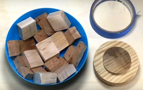
The basis is :
Prepping the mould with the wood;
Put in some means for the chuck jaws or screw chuck to grip;
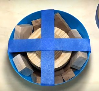
Tape the wood down so that it doesn't float away when the resin is poured in;
Mix the resin and hardener;
Stir in colour/sparkle as desired before pouring;
and leave for at least 24 hours.
(click for close up view)
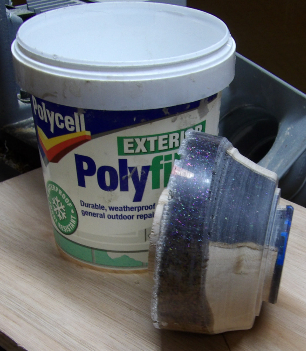
Next day, you should have something like Andy's photo above; the Polyfilla tub acted as the mould and he has already used the lathe to create a new spigot for the base of the bowl whilst mounted in the jaws using the wooden spigot partially buried in the resin. Andy had found that warming up the hardener/catalyst seemed to help it mix with the resin more efficiently and he advocated leaving the mix still for 15 mins to give bubbles a chance to dissipate. He had added a blue tint and some sparkles.
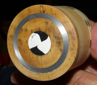
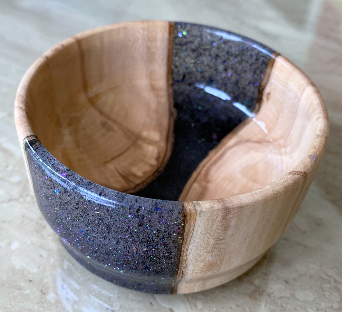
Much of the initial sanding of the resin piece was with a 50mm padded drill attachment but after fine abrasives and spray lacquer to finish, it looked like this ...
(click for close up view)
The July 2024 Competition was set to turn any piece of combination, decorative or integrated styles that incorporates two or more Mixed Solid Media
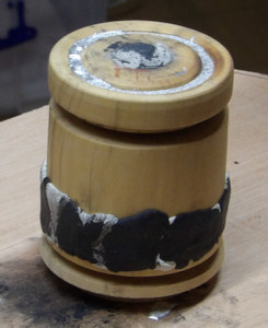
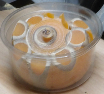 A
Cautionary Tale - Having seen some bamboo
stalks encased in resin on You-Tube, Andy told of his attempt to incorporate
this idea into one of his projects. To the left, you can see the pot
within which he had arranged a circle of bamboo to be set in some resin, somewhat
mimicking an orange. After allowing to cure and fitted into a chuck, Andy
experienced a catastrophic failure when upon starting the lathe, the resin
failed to hold the whole piece together and the orange suddenly broke up into 'segments'. You might spot in the photograph that some significantly large
pieces detached themselves and indeed there is one piece still in the workshop
somewhere he cannot find. The reason is uncertain but possibly a combination of
excess moisture within the bamboo and the thinness of resin bridging the edge to
the centre. As Andy is accustomed to do whenever he starts turning a new piece,
particularly with an irregular
shape on the lathe, he was wearing his face shield, which did exactly the job as
its name implies.
A
Cautionary Tale - Having seen some bamboo
stalks encased in resin on You-Tube, Andy told of his attempt to incorporate
this idea into one of his projects. To the left, you can see the pot
within which he had arranged a circle of bamboo to be set in some resin, somewhat
mimicking an orange. After allowing to cure and fitted into a chuck, Andy
experienced a catastrophic failure when upon starting the lathe, the resin
failed to hold the whole piece together and the orange suddenly broke up into 'segments'. You might spot in the photograph that some significantly large
pieces detached themselves and indeed there is one piece still in the workshop
somewhere he cannot find. The reason is uncertain but possibly a combination of
excess moisture within the bamboo and the thinness of resin bridging the edge to
the centre. As Andy is accustomed to do whenever he starts turning a new piece,
particularly with an irregular
shape on the lathe, he was wearing his face shield, which did exactly the job as
its name implies.
(photos by Rick
Patrick & Andy Ogilvie)
<to
index>
 Thu 16th May at MWCC Club Night
To clarify, you use Spindle tools when all the
wood grain of your piece is running parallel to the lathe bed.
Spindle
tools include :
Roughing Gouges (rarely used
full name is SPINDLE Rouging Gouge);
Spindle Gouges;
Parting Tools;
Skew Chisels;
Form Tools;
Roughing Gouges are designed to be used
only for spindle turning and NOT on bowl turning. They are tough
enough to take the knocks required to turn a square into a cylinder so long as
you're careful with how much you bite in one go. Taking a large bite will blunt
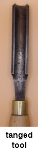
the tool edge quickly; taking too much could bend or break off the gouge. This
is because they are of relatively thin, forged steel and often tang-mounted into
their handles and despite their name, cannot survive such rough usage!
They come in various sizes but all are best used with the bevel ground to 40º -
45º; a common mistake is to sharpen the bevel at steeper angles which will end
up chopping the corners off badly and tearing the wood.
Use with the handle down and move the tool along with arms and body together
while rocking sideways on your feet. The toolrest hand can deflect shavings away
from the face. Too much down pressure results in an uneven jerking cut;
moving too quickly normally produces a spiral finish.
Next to consider is with the gouge perpendicular to the piece, the surface
getting cut is arriving straight onto the gouge and getting levered upwards
which leads to a less than smooth tool finish. This is helpful for quick removal
but for the final pass, holding the gouge so that it is angled about 45º from
the perpendicular, the cutting edge is presented like a skew which will now
leave a shiny smooth finish. With a careful steady hand, you will produce a
straight surface. The only other shapes to make on a spindle are 'beads' and
'coves' with .....
Spindle Gouges. A bead is started by just
rotating and rolling the gouge anticlockwise along the toolrest for the left
side and similarly clockwise to form the right side of the bead. These movements
will only cut an arc equal to its bevel angle. To cut beyond that arc, the
handle has to be moved and lifted (because the diameter has become smaller) in the same direction and in coordination with
the rotation so that the gouge tip and bevel end up perpendicular at the desired
edge of the bead. This means the handle end has overtaken the tip.
For a cove, start with the gouge on its side, flute towards the intended cove
and use your fingers on the toolrest to balance & guide as you rotate the gouge
to end flute up at the bottom of the cove. As with the bead, the movement
requires coordination of slide across toolrest with rotation, handle descending
and when approaching the bottom, a conscious gentle push into the wood for the
bevel to stop the tip from digging in and producing a pronounced line where the
opposite cove side ended. Tools with long handles normally provide better tip
control - for every inch the handle moves the tip around the toolrest hand, the
short tool affects the tip movement far more than a long one. However, with
beads and coves requiring so much hand steering, a short tool makes it easier to
manipulate without your body getting in the way. Unfortunately, if the tool's
flute is short because of the metal has been ground back so many times, it may
be short but you are probably cutting with high speed steel rather than the
hardened which keeps its sharpness for longer use.
This gouge can also produce a straight surface by using your fingers as a
resistance or brake while your handle hand steers the tip so that it remains at
the same angle and distance over the toolrest with the cut running level. When
cutting towards the left, It is important for the flute to be angled towards
your left shoulder such that the cutting edge is just left & lower of tip centre;
likewise when cutting towards the right, use right shoulder and just right & lower
of tip centre.
 Parting Tools are regularly used to
accurately block out a smaller cylinder guided by callipers. They come in
various shapes in an attempt to avoid friction when cutting wood which leads to
swelling up and binding/grabbing on the sides of the tool.
Parting Tools are regularly used to
accurately block out a smaller cylinder guided by callipers. They come in
various shapes in an attempt to avoid friction when cutting wood which leads to
swelling up and binding/grabbing on the sides of the tool.
Skew Chisels come to the rescue of a clean
finishing cut across the end grain of spindles. Parting tools tend to tear out
the end grain unless the wood is particularly close. With a Skew, you must only take off thin
bites at a time so that the removed wood is a thin disk being skimmed away.
Skews can also cut along the grain with a bit of care. Production turners
of yore and the Seiffen wooden Christmas Decoration turners of Germany today
used Skew Chisels for most (if not all) their
shaping. Skews come in many bar shapes and widths. As most of us have missed out
on the 3 year apprenticeship of Seiffen folk, the occasional user should select
a small width bar which has the advantage of producing a lower rotational force
in your hand than a wider bar would.
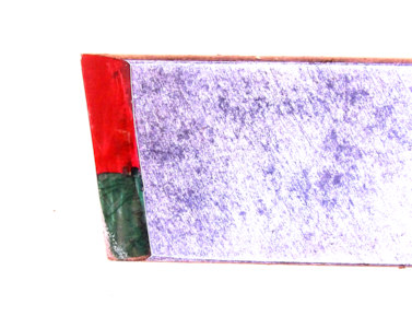 At all times, you are trying to avoid the
wood grabbing the cutting edge and twisting the tool out of your hands. This is
best achieved by raising the toolrest so that only the lower third of the tool
is in contact with the upper quadrant of the piece. In the photograph to the
right, you will see that when the trailing corner edge is being well
supported by the toolrest, the Skew is cutting away the wood with minimal
twisting force and neither corner is in danger of getting snagged. Keeping
wood contact within the green area makes the cut stable. Touching in the red area
is liable to twist the bottom edge of the tool off the rest and out of control.
At all times, you are trying to avoid the
wood grabbing the cutting edge and twisting the tool out of your hands. This is
best achieved by raising the toolrest so that only the lower third of the tool
is in contact with the upper quadrant of the piece. In the photograph to the
right, you will see that when the trailing corner edge is being well
supported by the toolrest, the Skew is cutting away the wood with minimal
twisting force and neither corner is in danger of getting snagged. Keeping
wood contact within the green area makes the cut stable. Touching in the red area
is liable to twist the bottom edge of the tool off the rest and out of control.
Another useful cut with a Skew is a V-cut to transition the square top section
of a table leg (aka pommel) into the largest circle that the square timber can
form by enlarging the V shape until the groove is so deep that it nearly meets
at the centre of a flat side.
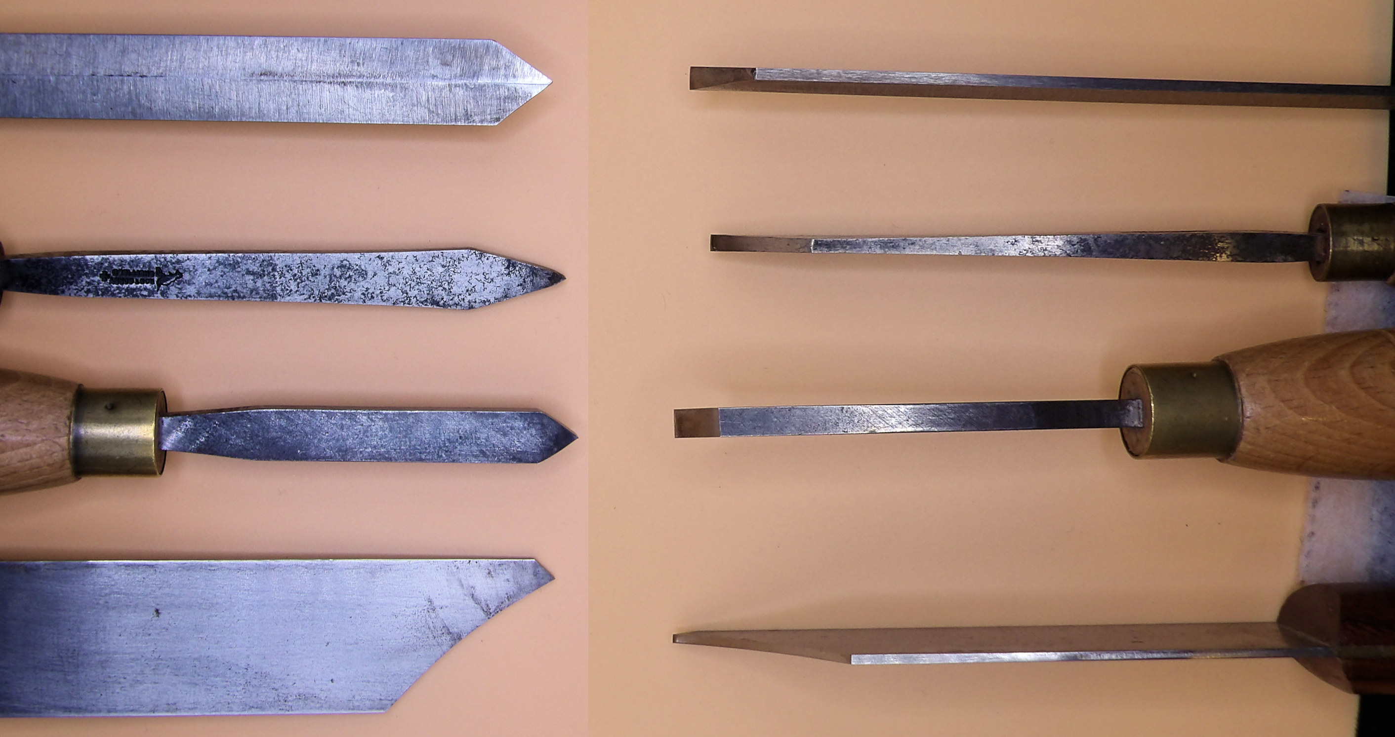
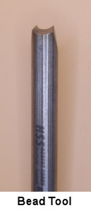
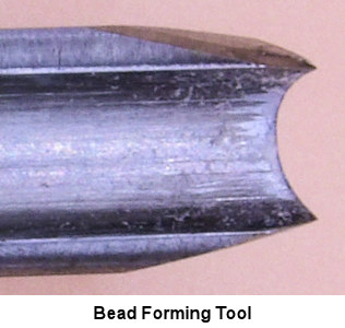
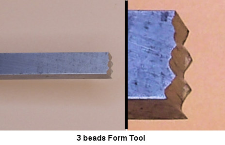
Form Tools - usually bead forming tools
are fine until they are used on soft woods. When they are wriggled from
side to side and the tool has cut down to near the crown of the bead, there is a
likelihood of the grain to chip out on opposing sides where it was very short and
parallel. The Spindle Gouge will make a better job with soft wood. The photos
below show how the Bead Tool is presented to the piece, i.e. groove downwards;
to help the wriggle action described above, note the outer wedge shape grind in
the 2nd photo and the last shows some home-made Form Tools, although the lower
is making use of the last bit of the flute so it is likely to be primarily mild
steel rather than the treated hardened steel that was there when first bought.
Another tool
(popular in USA) that can be used on spindles are Solid Tipped Carbide Lathe
Tools although they seem to tear most of our native timbers, but good with close
grain wood types.
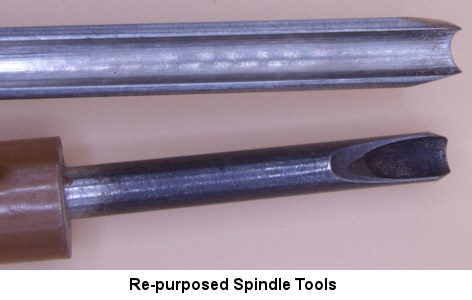
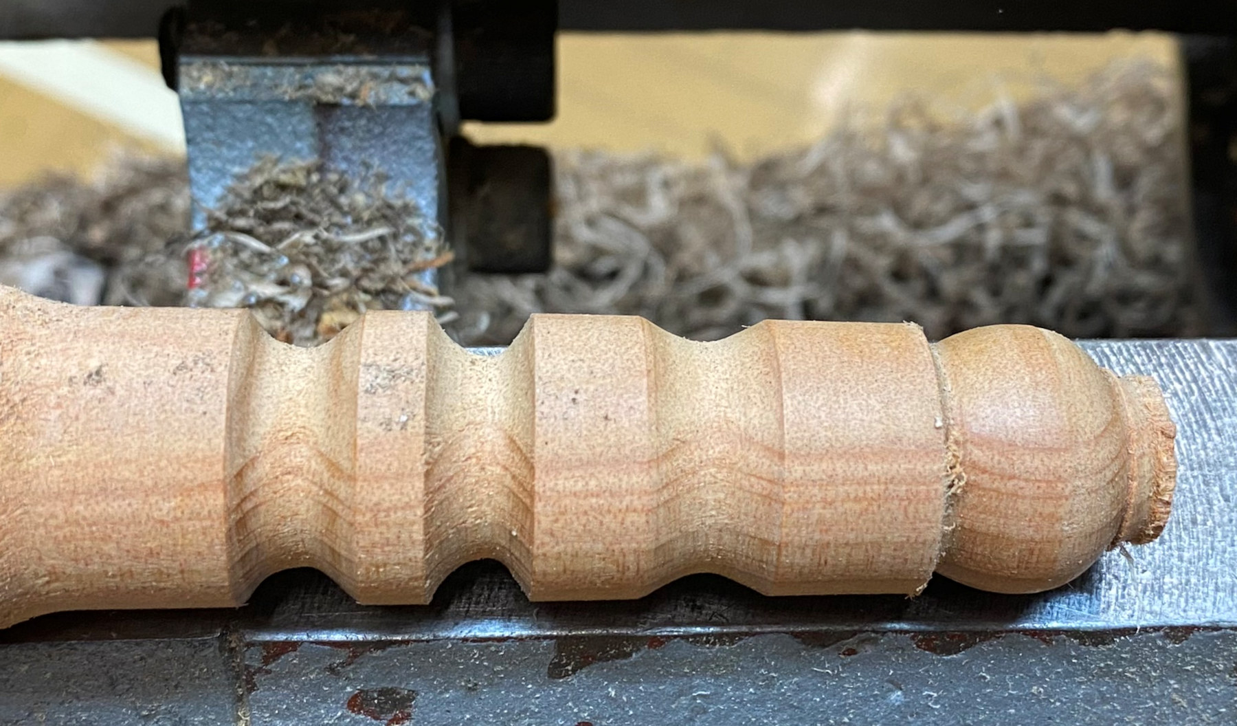
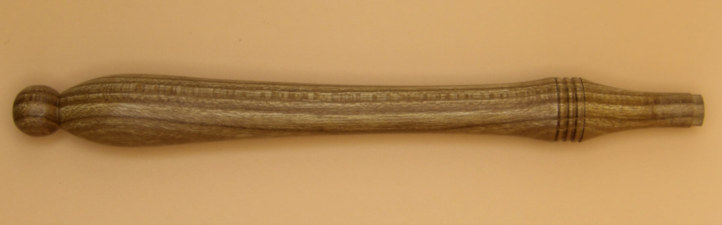
Paul then produced a Policeman's Truncheon as an ideal project to perfect all the spindle shapes discussed above.
(photos by Rick
Patrick & Paul Reeves)
<to
index>
May 2024
DEMO 1
Gavel with
Paul Reeves
Thu 16th May at MWCC Club
Night
As there were several newcomers to the Club, Paul started off with some
Revision of Spindle Work.
An account of this subject can be found <HERE>
Honorary Member, Greta Reeves worked many years at Lymington Auctions and it
became practice that her boss would arrange for a replica of his own
Auctioneer's Hammer be turned as a retirement gift for long standing employees.
His original was of Cocobolo but the replicas were turned from more readily
available Laburnum. This original was tactile & small enough to grip the head
comfortably in his hand. Consequently, the handle didn't have to cope with
much blunt force and didn't need a strong thick connection to the head. The 3
examples below are Box, Laburnum and Mohonia.
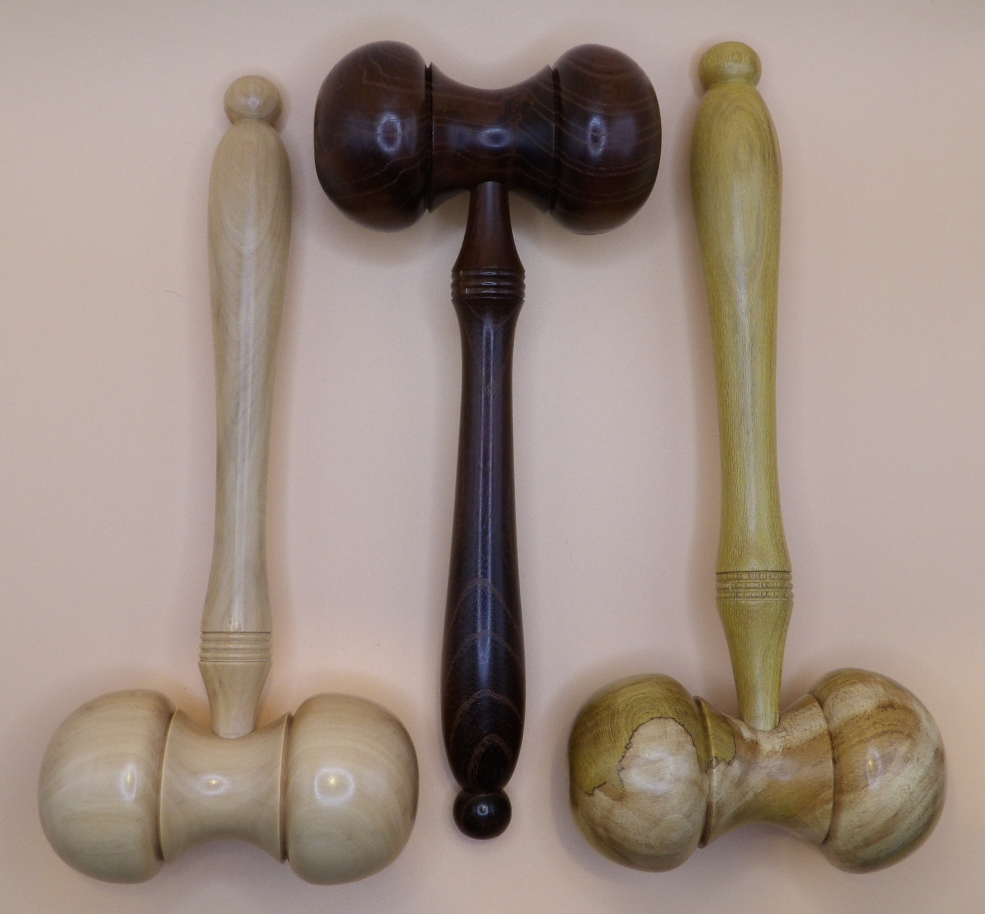 The
head and the handle are both spindle components turned separately and
subsequently glued together.
The
head and the handle are both spindle components turned separately and
subsequently glued together.
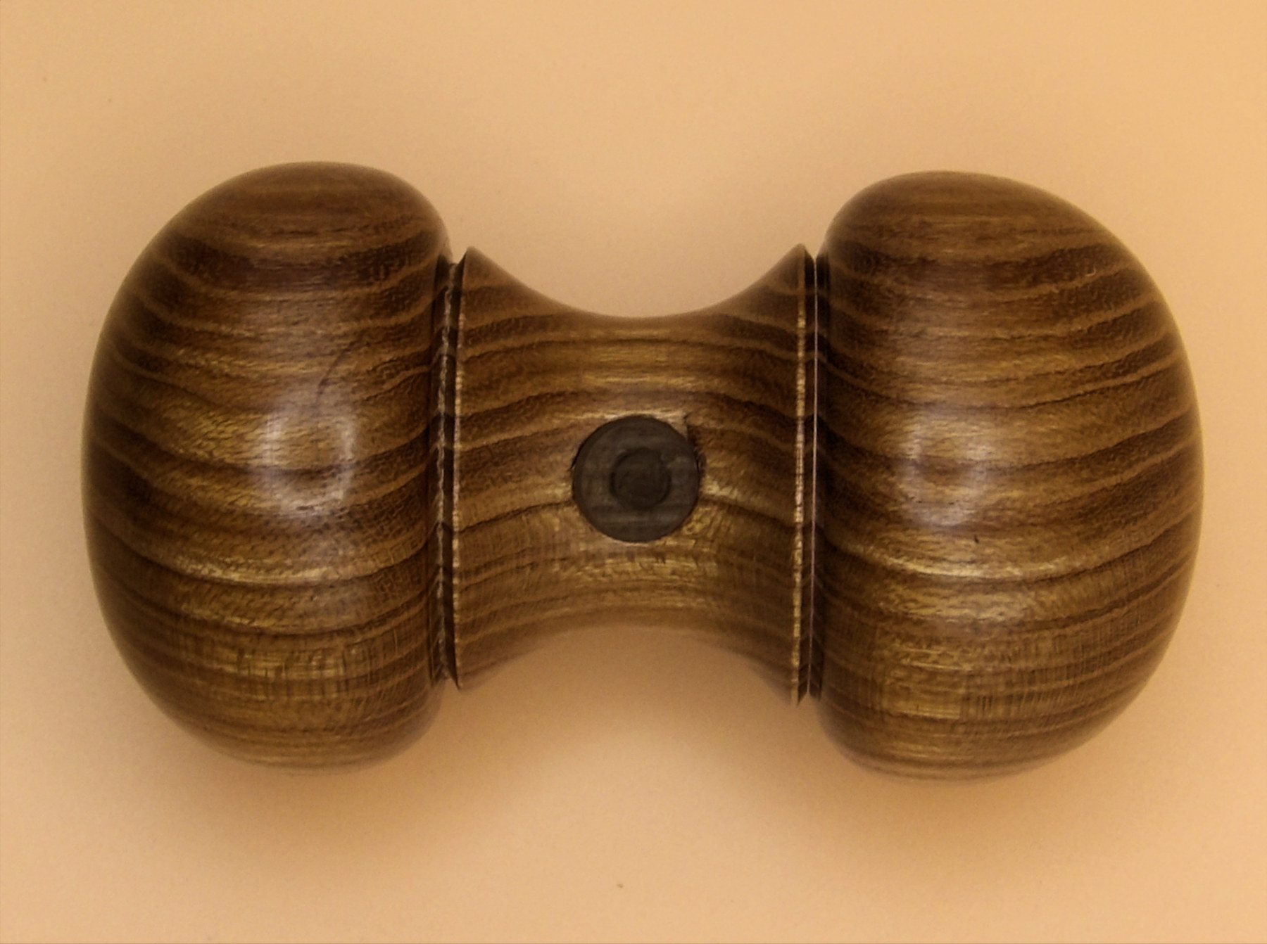
Despite recent demonstrations venerating the 'Golden Ratio' of 1.618, the
dimensions of these gavels are such that the handle is twice the length of the
head. The length of the head was twice its own diameter. Additionally,
dividing the head into four gives a far better proportion for the two hammer
faces taking a quarter of the length each, leaving the neck between them for the
remaining half.
Head
A prepared cylinder of Laburnum was mounted between centres. Paul advised
against using sprung steb centres at either end as he found the sprung central
point applied to end grain tended to split the piece when under tension.
He had planned this project to have a 1½" face diameter, 3" head length and a 6"
handle.
He used a narrow Parting Tool to mark out the ends of the head and pencilled in
the quarters between them.
Using a wide Parting Tool making half-width overlaps, Paul quickly removed waste
from the neck.
Having prepared callipers to ¾" for the diameter of the neck, he used the
Parting Tool to finish blocking out accurately.
As both hammer faces were to be near spherical, he pencilled in marks around the
piece about ¾" from each end which is where the face would be at its maximum
diameter.
He then started making bead-like cuts off the ends gradually working back
towards the pencil line but leaving it visible. It was important to avoid
getting the end pointy; it should look more like a puffed-up cushion. The final
cuts were made while maintaining a slow, smooth and light-touch pass with good
bevel contact throughout. If your hands end up moving quicker than needed, the
bevel will lose contact/support and the tip will catch the wood and dig in.
The trick now was to turn the other end to match! If you have changed
hands when holding tools to work in the opposite direction from your early days
of turning, you will find that very helpful in this case.
 The
next details were to put in a small cove centrally where the handle will go and
to finish off the hammer heads from the pencilled line back towards the neck.
Paul favours a small decorative feature in these beads called a quirk, which was
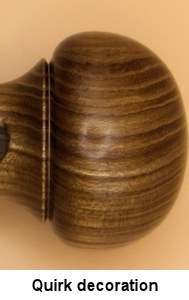
achieved with a 2mm ridge left about 20º down from the pencil lines so that a
Skew could create a shallow crisp-edged V-cut and the bead continues down to the
neck. This was only a tiny detail but it certainly helped to focus attention on
the heads.
The
next details were to put in a small cove centrally where the handle will go and
to finish off the hammer heads from the pencilled line back towards the neck.
Paul favours a small decorative feature in these beads called a quirk, which was
achieved with a 2mm ridge left about 20º down from the pencil lines so that a
Skew could create a shallow crisp-edged V-cut and the bead continues down to the
neck. This was only a tiny detail but it certainly helped to focus attention on
the heads.
One might think it more sensible to drill the hole for the handle earlier -
perhaps even while the Laburnum blank was a square. However, now that the
current dumbbell shaping is nearly finished, the patterns of the grain lend
themselves for you to decide where to drill the hole in order to show them off
to their best when the gavel is at rest on a desk. Once marked with an awl or
similar, one could finish the sanding and drill the hole once removed from the
lathe. For the demonstration, Paul drilled the hole on the lathe by eye using
smaller drill bits as pilots and gradually building up to the final size.
Using a Skew, he decreased the supporting end nibs to about 4mm diameter which would be strong enough to hold the piece while sanding. With the lathe speed reduced to alleviate the piece overheating while sanding, Paul prefers to follow the curves by supporting abrasives underneath the piece and taking care to avoid sanding away detail and decoration by sanding the shape and not sanding to shape. Laburnum will abrade down to 1200 grit or finer with considerable success but Paul was going to finish this piece with buffing so down to 400 grit was going to be sufficient.
Handle
Another prepared cylinder of Laburnum was mounted between centres. Once again,
Paul avoided using steb centres following a previous attempt turning a Mahonia
cylinder down to an 8mm tenon for inserting into the head, because it split as
soon as he tightened the tail stock.
He aimed to carry out all the shaping and decoration prior to weakening one end
as a result of the small tenon being turned. Paul also advised that if the
intended gavel was to be used while holding a longer handle rather than a grip
around the head, you might want to consider reinforcing the tenon with a steel
brad/nail.
He also planned to turn the piece with the tenon at the tail stock end so that
when checking fit into the head, it could be easily remounted in the lathe for
further turning.
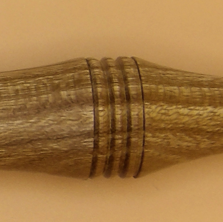
The decoration was a homemade creation from an old square-ended scraper with 3
grooves made with the corner edge of a grinder wheel. This results in 3 evenly
spaced and shaped tiny beads. Because he had carefully spaced the grooves
relative to the width, he could easily increase those matched beads to 4 (or 40
of them if you wanted) by using a previously cut bead to fill an outer groove of
the tool and guide further matching cuts.
An elegant handle is all about shape and curves. Paul used a thin Parting
Tool to mark out the ends, the tenon and the diameter of a spherical shape at
the bottom end. He quickly turned away the bulk to leave a rough shape before
changing to a short Spindle Gouge to refine to the shape below. Be aware
that keeping the tips of narrow spindles cutting at the optimum height on an up
and down surface isn't easy and needs a gentle contact pressure throughout to
avoid digging in. With close grain woods like Laburnum, there will be minimal
compression of the spigot so that requires starting from slightly oversized and
gently approaching the necessary diameter with regular retracting of the
tailstock to check the fit into the head.
When satisfied with the cut shape, start sanding up to the edge of any
decoration but be careful not to wipe away small beads and sharp corners,
particularly with your initial grits; they can be polished up with the edge of
the finer grits when you progress to them. Whenever sanding spindles with
the lathe turning, keep the abrasive moving and keep in mind that it is sanding
across the grain fibres so they will inevitably stick up. A technique to
overcome this tendency is to stop the lathe and finish that grit along the grain
before changing to the next. Don't sand the spigot because if it fits, you won't
want it made smaller and besides, a very smooth finish doesn't help the glue to
adhere to the wood.
A Skew reduced the ends with a series of enlarged V-cuts to a very small
diameter (still stable because the wood is so dense) and finally parted off with
a fine toothed saw aimed away from the piece so that the tiny pimple left was
abraded away with the last grit used.
The head and the handle were buffed
with a light touch using a buffing compound so remember to put on personal
protection in order to avoid getting grit flying into your eyes. Remember to
buff off a surface, not into
it, or else the piece is liable to be ripped out of your hands. The final finish
was some micro-crystalline wax.
When sticking the handle and head together, thought was taken to line up their
grains sympathetically.

(click for closer view)
The June 2024 Competition was set to produce a Gavel
(photos by Rick Patrick & Paul
Reeves)
<to
index>
I found it difficult to picture in my mind how to get 3 symmetric points out of
a solid with 8 vertices, 12 edges and 4 sided faces but then I remembered
something cubed is renown as a power of 3 and it does have 6 faces.
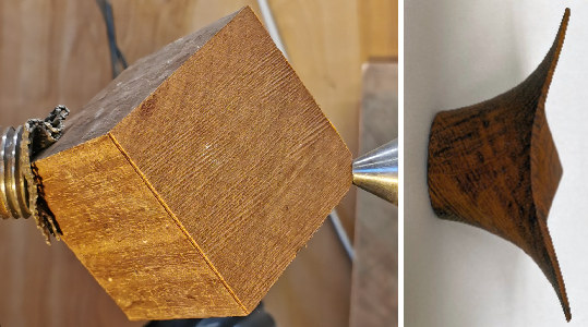
When Andy showed a finished 3-Point bowl alongside a perfect cube of wood,
one could clearly follow that the cube had somehow to be mounted symmetrically
between diagonally opposite vertices.
It was important that your starting cube of wood had 3 clean adjacent edges
because a small part of those edges furthest away from their common vertex would
comprise part of the finished piece.
It is possible to turn a thin walled bowl dependent upon the chosen wood.
Andy's example was of Brown Oak, which was close grained whereas an open grained
wood like Ash would prove difficult.
Andy had prepared a cube of Hornbeam with each edge of 100mm. This would
produce a finished piece whose points would be within a maximum 163mm diameter
circle. (Ratio of edge to span = 1 : 1.63 from Trigonometry)
Having decided upon the 3 clean adjacent edges, he proceeded to saw off the tip
of their common vertex in order for his tailstock to maintain a firm hold.
The opposite vertex was jammed into the headstock spindle with the aid of
non-slip matting. He took care to ensure the headstock end was in its correct
position by checking, using his toolrest, that his chosen 3 vertices were passing it at
the same position.
Top Tip
: Once the lathe is turning, these angled edges will fade from
view so be careful to keep fingers on your side of the tool rest.
Also, with it turning, you won't be able to see exactly when the gouge will
start to cut so ensure that first contact is always with the gouge's bevel as
you slowly move towards the piece with the handle held low. Upon contact, the
bevel will make a 'bumping' noise which will suddenly dissipate when you
gradually raise the handle and the gouge tip starts to cut.
Andy started turning away the 3 vertices nearest the headstock by taking thin cuts with each pass in order to avoid rip outs
as each edge reached the cutting tip. A high lathe speed always help with
irregular surfaces but it is important to avoid any 'greedy' deep cuts.
The spigot was to fit his 40mm set of C-jaws with a 7mm depth. Andy used his
thin parting tool to create the groove for the jaw lip at the bottom of the
spigot and then a similar groove half way up; this was for a later process.
Andy initially sanded with the lathe turning while using a power sander rather
than hand held abrasives in order to avoid the remaining sharp corners causing
injuries. He then stopped the lathe and hand sanded along the grain before
finishing with a coat of sander sealer.
The piece was then fitted into his C-jaws ready to hollow out the bowl. Andy
sawed off the newly exposed tip to accommodate support from his tailstock.
Taking care to avoid flying corners, he gradually turned away towards the centre
but leaving a stub for his tailstock.
As he cut closer to the flying corners, he regularly stopped the lathe to check
that his inside cut was keeping parallel over the entire length of the outer
edge of the piece. Any disparity quickly showed just how far down the cut
his Bowl Gouge needed to remove more wood to return the edges to parallel.
Halfway through the hollowing, Andy turned his toolrest into the hollow to avoid
a long over-hang of the gouge near the bowl's bottom.
Once satisfied with the inside parallel shaping, he removed the tailstock as
well as the stub to about 5mm from the bottom. Using a smaller Bowl Gouge,
he continued cutting to clean up the bowl's centre with just the chuck jaws
supporting.
When it came to sanding, Andy took care to avoid the abrasives
damaging any of the sharp edges. He didn't do any hand sanding with the
lathe turning, instead used his selection of various hard-backed shaped pads
without applying too much pressure. He found that his power sander with a
soft padding was ideal for sanding the central bottom of the bowl when applied
to the opposite side of where he was standing. With the lathe stopped, he
hand sanded to finish but again being careful of downward pressure near the
edges.
The piece was sander sealed and when dried, microcrystalline wax was applied
using some webrax.
The piece was repositioned so that the C-jaws now engaged the mid groove (formed
when turning the spigot initially) which made the parting off an easier process.
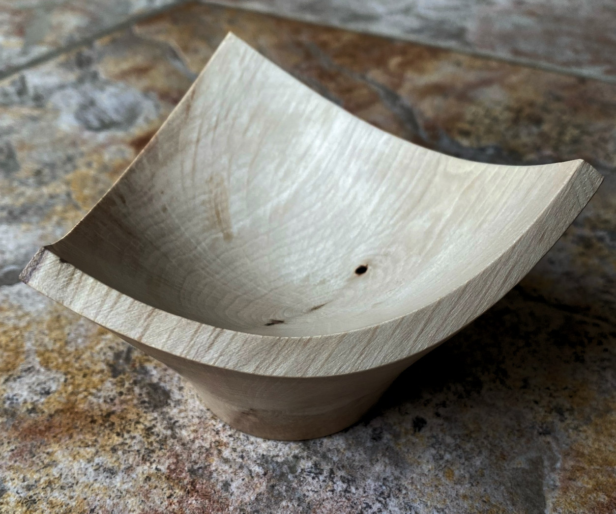
(click for close up view)
(photos by Rick Patrick, Andy Ogilvie &
Allan Rae)
<to
index>
January 2024
DEMO 5
 Racing
Cars with
Andy Ogilvie
Racing
Cars with
Andy Ogilvie
Thu 18th Jan at MWCC Club Night
Design Plan
Andy described his own design as an example of what the woodturner needs to
consider.
The basic form of the bodywork is obviously a cylinder with a slightly reduced
round flat at the back end but with more reduced shape at the front end.
Andy wanted a flattish bottom to enhance the shape and reduce wheel diameter
required to clear the underside. He, therefore decided to glue two wood
blocks with the idea of offset turning to leave ⅔ upper body height of Sycamore
and ⅓ lower body of close grain window wood. The contrasting
coloured woods would help with the end decoration while the offset would lead to
the bottom block being left flat.
The next option to consider was whether to incorporate 4 individual axle-wheel
assemblies or 2 individual axles drilled through the body with a wheel at either
end or some other method. Clearly, it is down to you to decide which design will
create the least friction. Then whether the wheels were to be all the same
or different sizes from front to back, which in the latter case, would require
careful planning of where the axles were to join into the body.
Although the 'race circuit' hall floor will be perfectly flat so ground
clearance of a long wheel-base shouldn't be a factor, but a long thin car body
might
not be helpful when propelling by thumb and neither attractive nor a
realistic car shape. However, cars like an Austin Mini were very stable
with a wheel close to each corner. Andy planned a finished length of about 150mm with 2
axles about one fifth the length in from either end.
Body Construction
Andy had prepared the glued segmented rectangular blanks and had drilled two 8mm holes
about 30mm from the planned finished ends (i.e. allowing surplus to accommodate
the mounting centres) for 2 axles to go through the body at identical heights so all 4 wheels
are to the same diameter. He drilled a further 20mm hole about a
third of the way down the top from the back end for the cockpit. Doing this while the blank was
still rectangular made the job of getting all these holes exactly at right angles
to the body a lot easier.
He also drew on the intended back end, an arc to delineate the uppermost extent
of the bodywork.
He had found the central point of each end and made marks about 10mm towards the
bottom block at both ends.
To reduce the chance of the drive centres splitting the block apart at their
joint, he used a Pro Drive Centre in the head stock and a Ring Point Live Centre
for the tail stock to mount the blank between these offset centres.
Top Tip
: As Andy was right-handed and the front end of the car would
be 'downhill' from the larger back end, it made sense to mount the car's front
end into the head stock centre so that as he moved his gouge from right to left,
he would be cutting down the lie of the wood fibres.
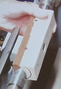
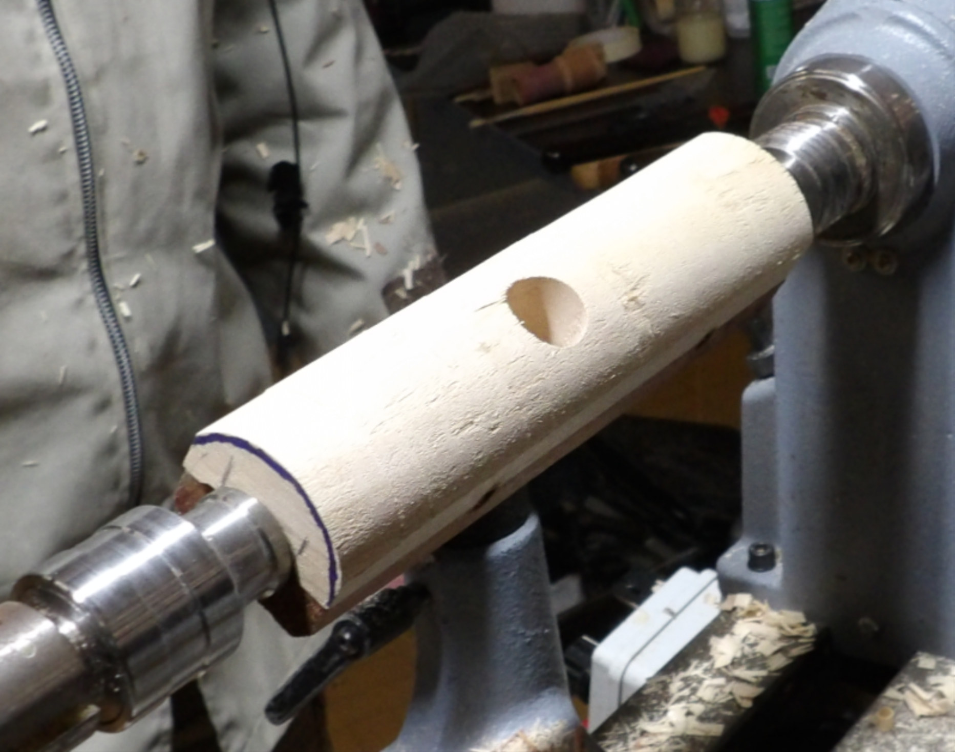
The block was now turned down to the pre-marked
arc on the back end using a Roughing Gouge or a Skew Chisel. For the
demonstration, Andy used a planing cut with a Skew. Whichever tool one
used, care has to be taken to avoid using too much downward pressure into the
wood or else the pre-drilled cockpit hole will allow the tool to cut deeper into
one side of the hole.
Once he had turned a cylinder with just the bottom having a flat surface, Andy
used a Parting Tool at the intended front and back of the car to create some
working space for his Spindle Gouge to the rounded wedge shape in the photo
below.
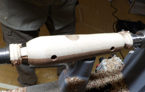
The front end was detailed and left flat as shown in
photo below
for a radiator decoration to be added later.
The back end was left flat for exhaust pipes (pimping/embellishing an otherwise
plain back) to be added after the body had been parted off.
But before that, Andy reduced the lathe speed and used some abrasives via a
backing pad to protect hole edges He removed the dust before sander
sealing
the body to prevent any colouring bleeding into the wood.
Once that had dried, he applied some decoration while still mounted between
centres so that he could use the tool rest as a guide for marking in some
'go-faster' coloured straight stripes between the axles and an outline for the
engine bay.
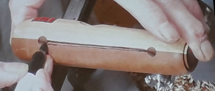
Once parted off, used more abrasives and sand sealed the ends, Andy finished off the body decoration by drawing a radiator on the front end, remembering to add a 'race number'.
Axles & Wheel Nuts
The car body width ended up as 40mm wide so Andy allowed for additional
20mm per wheel per axle which totted up to 80mm axle length required. The
car body had been drilled with an 8mm bit so with a blank of over 80mm long
mounted between small centres, Andy prepared to turn an 8mm dowel but with the
headstock
end about 15mm diameter.
To maintain a length of wood to be a constant diameter does need a bit of
preparation. A common way is to use a Parting Tool and callipers set to
the required diameter and carefully reduce the oversized cylinder every 30mm or
so down to the required diameter and then join up the indents by cutting away
with a Spindle Gouge. However, Andy elected to demonstrate a method using
a spanner instead of the callipers by using an 8mm open-ended wrench.
Indeed, some people have shaped and sharpened their spanner's jaw tips to do the
cutting at the same time as the sizing.
Top Tip
: As most spanner jaws are deliberately manufactured very
slightly oversized for the sake of easy fitting, this feature helps one to avoid
turning away too much and the correct final size is achieved with a block and
abrasive. But bear in mind that most drill bits for similar reasons are
very slightly undersized.
After parting off the axle leaving a
small width of 15mm diameter to retain a wheel on its axle, matching Wheel Nuts
to match the other end were turned from the remnant blank transferred to a pin
or else o'Donnell chuck. The 15mm blank was first drilled out with an 8mm
bit held in Jacob's Lathe Drill Chuck before finally parted off.
Wheels
Having planned for all four wheels to be of 40mm diameter, Andy started with a
suitable rectangular blank (which he had pre-drilled at home using an 8.5mm bit
to ensure a loose fit on his 8mm axles for the sake of reducing friction), held
between chuck jaws and a point centre tailstock. This was accurately
turned down to a 40mm cylinder before carefully marking out identical widths to
allow a production line of wheels. Each wheel first had its outer face
cleanly cut with a Skew to shape the tyre and hub, a Point Tool to create the
join between tyre & wheel followed by burning by wire or Formica to create a
tread effect, then a small Spindle Gouge to create a curve of the inside face
down to a 15mm diameter to ensure the tyre avoids fouling the bodywork and
finally parted off to repeat the process another three times.
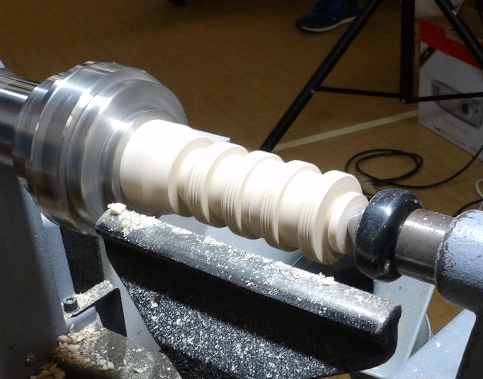
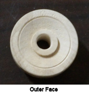
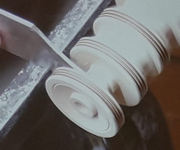
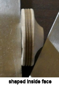
Exhausts & Driver
Andy drilled two 6mm holes in the back of the car body and with a suitable blank
between jaws and point centre tailstock, he used a Parting Tool to create a 6mm
dowel, a flared shape for the silencer and in again for the tailpipe.
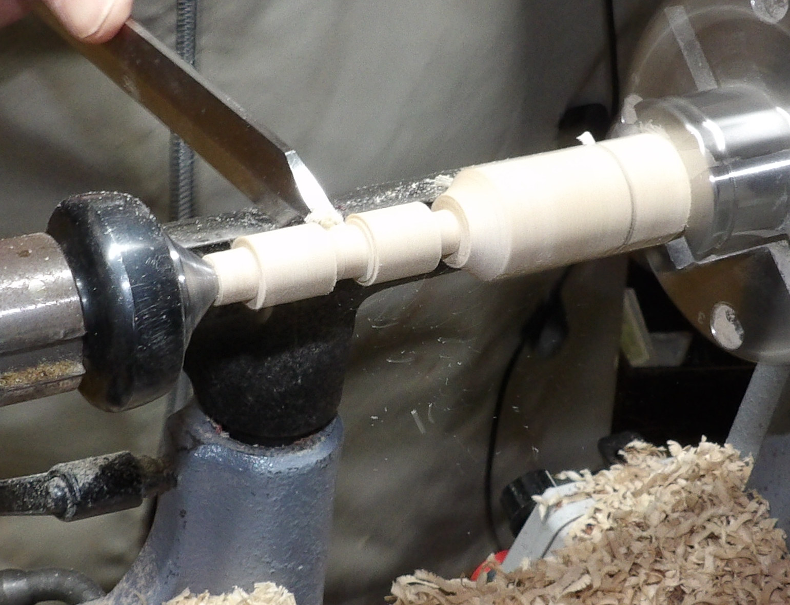
For the Driver, the Exhaust blank was now turned
to the diameter of the previously drilled cockpit hole and a head shaped in the
first 10mm, narrowing to a neck for the next 5mm and then back out towards the
body diameter. After measuring the depth of the cockpit hole, parting off was
done so that the driver's shoulders would just appeared above the coping.
Andy then used a drum sander to create a dip on the top of the
body behind the line of the front axle and in front of the cockpit (see photo
below); this dip
would be where one's thumb could launch the car forwards.
All parts were cleaned up with fine abrasives paying particular attention everywhere there was a possible source of friction. Every part had its fitting checked before being sander sealed and allowed to dry thoroughly.
Assembly
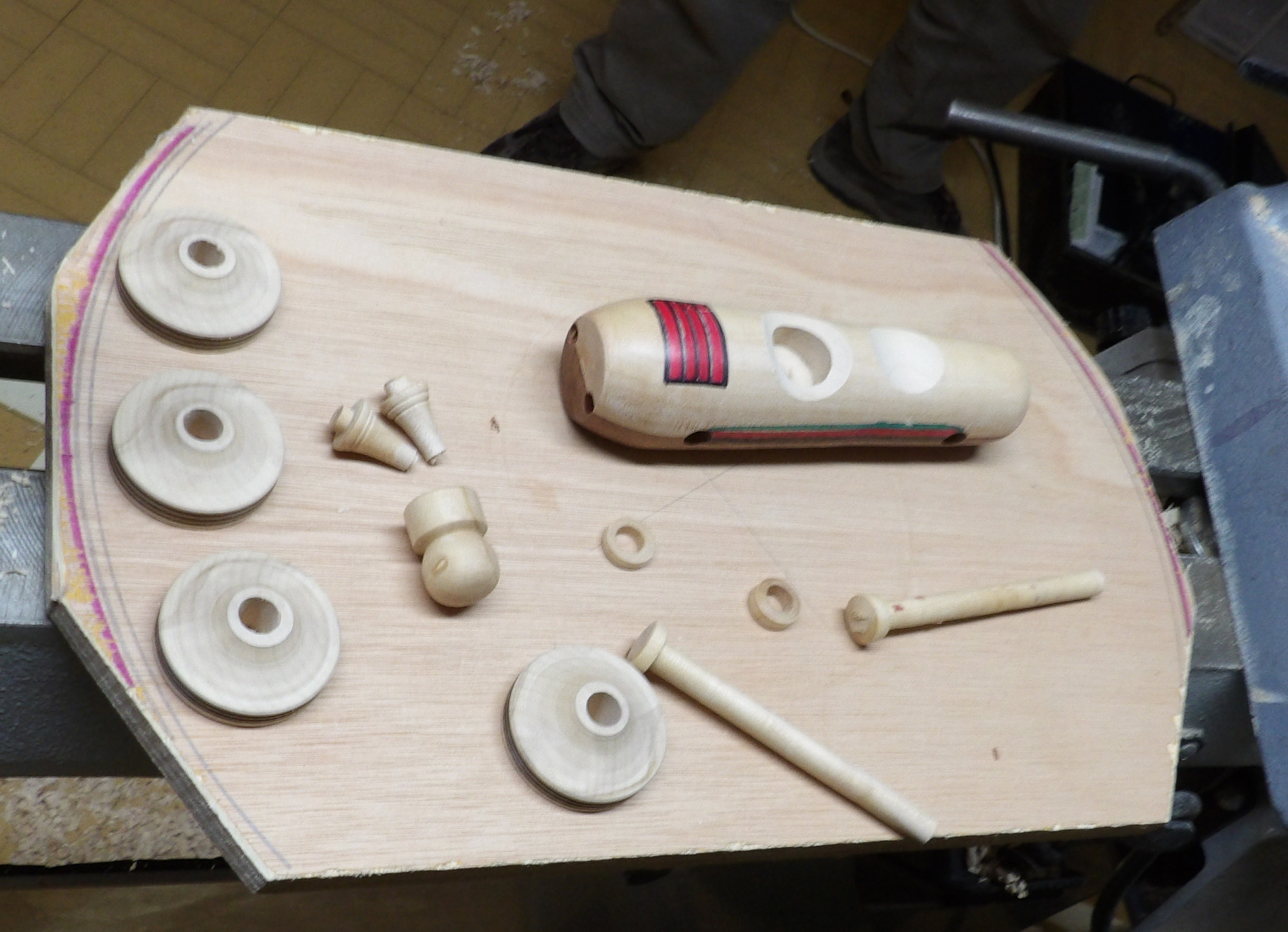
It was now a case of finishing the colouring and
decoration before superglueing the various parts together.
Wheels were threaded (once correctly orientated) onto its axle before the latter was
glued to the body with just enough room for the wheel to turn freely.
The opposite end of the axle had its wheel correctly orientated and the Wheel
Nut similarly glued for that wheel to turn freely.
The axles were then trimmed and ends sanded.
Exhausts & Driver were the last to be glued in.
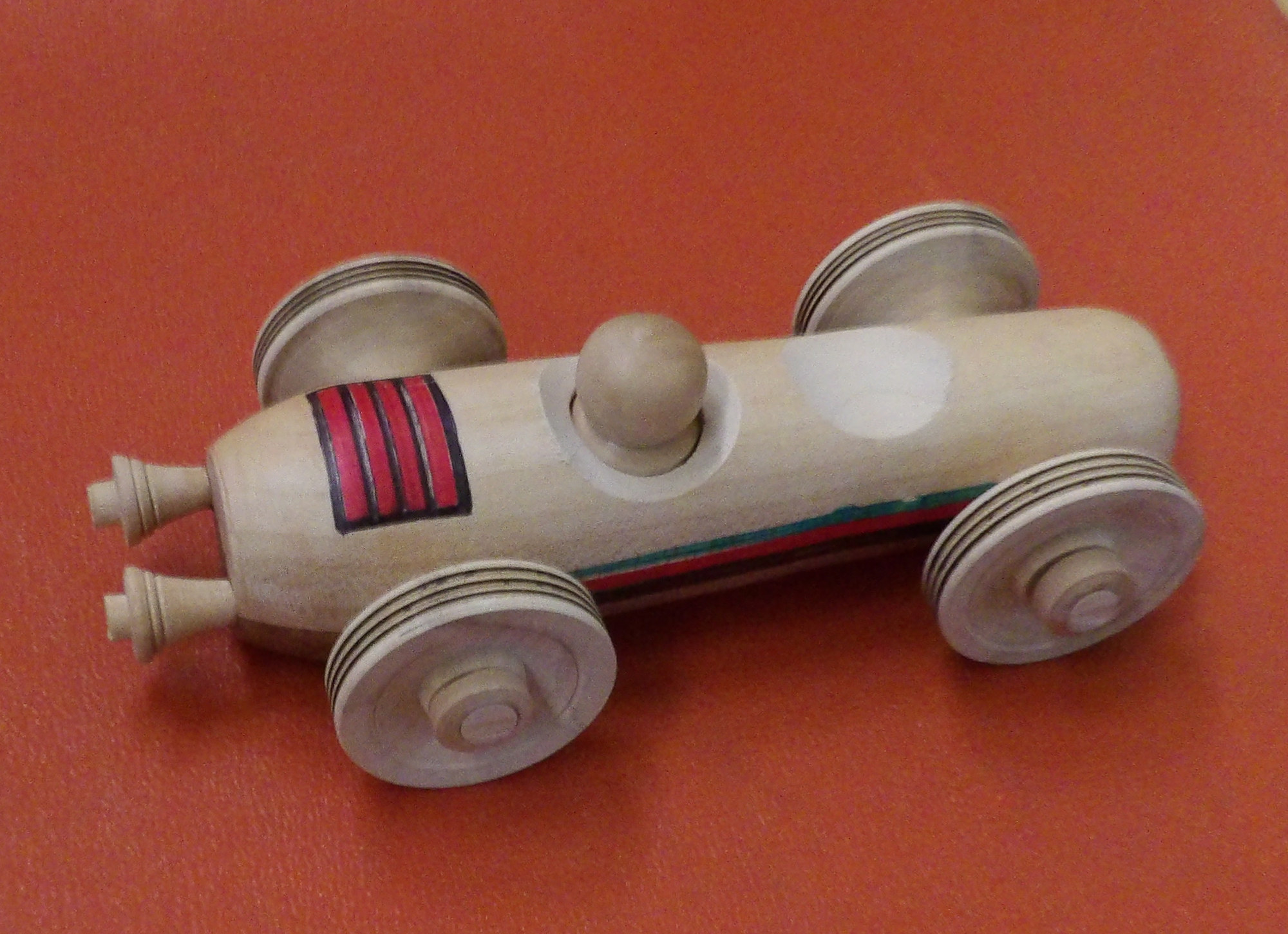
The February 2024 Competition was set to produce a decorated Racing Car entirely crafted in WOOD by you, shaped like a car and able to race in a straight line with a flick of one's thumb/fingers.
(photos by Rick Patrick, Andy Ogilvie & Ian Wright))
<to
index>
December 2023
 Light
Bulbs in wood with
Paul Reeves
Light
Bulbs in wood with
Paul Reeves
Thu 21st Dec at MWCC Club Night
Paul started with a philosophical thought about
tonight's demonstration. Wooden objects can have a surprisingly long life. In
fact a Roman peppermill had been found at Hadrian's Wall and was still in
reasonable condition; there were also elaborate wooden artefacts in several
Pharaoh's tombs. It's a sobering thought that one of our own creations could be
around in hundreds of years time so perhaps we ought not to ignore that little
pimple or dimple in the bottom, else in years to come someone will be wondering
why we didn't take that extra time to get it right.
His Christmas demonstration was something a little different. He started by
commenting that Tungsten light bulbs last about 2000 hours, LED lamps 20,000
hours but his light bulb tonight could last as long as a Pharaoh's artefact.
He had chosen a piece of Hornbeam (which usually takes a good thread) mounted
between o'Donnell jaws and supported by a tailstock before using a Roughing
Gouge to turn a cylinder. In order to create a clean smooth surface, a Skew
Chisel with the point down was pushed across the end just short of the tail
stock.
Top Tip
: If making a string of bulbs, be sure to note the measurements
for replicating. The bulb dimensions look realistic if their length is about 1¼
to 1½ times the width and a 10 tpi chaser or similar is used.
A Parting Tool was used to reduce the end 2cm of the cylinder for the lamp
thread.
One could easily represent the thread with miniature beads but why not use
chased threads to give an authentic appearance. For a working screw thread, one
would normally leave a space at the left-hand end of the spiral so that the
chaser could be withdrawn from the cut in a continuous movement without
risking the threads tops snagging as the chaser hits the stops! This
thread is never going to be used so worn tops are of no concern.
The lathe was slowed to about 300-350 RPM and the
chaser was 'landed' on the piece with the leftmost 2 or 3 cutting edges touching
while Paul was smoothly moving the chaser from right to left but quickly
retracting before it buffeted against the larger diameter. He finished
with abrasives gently over and in between the threads to clean away any fibres.
Once completed, Paul moved the tail stock away and ensured the end centre point
was distinct before upping the speed and using a small Spindle Gouge to shape
the 'lead blob' at the very end of the thread while leaving the indent available
so that a hole could be drilled to allow for an eyelet screw to be subsequently
twisted in.
Returning to his ⅜" Spindle Gouge, he first turned a curve down to the thread
and then his 'long curve' technique was to very gently swing the tool handle
towards his body while keeping the cut tracking along the centre line aiming to leave enough
wood to support the piece (say 5-7mm) almost at the desired length. Paul
warned that while the shape might look fine horizontally on the lathe, it's
sometimes worth unscrewing the chuck off the head stock and stand the piece
upright to check how it looks in the direction it's going to be hanging.
Abrasives down to 400 grit were applied because the 'glass' surface has to be as
smooth as possible for colour to cover evenly right down to the line where it
fits into the 'metal thread cap' (created with his Skew). If it's not flat
enough, the colour will sink deeper in the grooves and won't end up an even
shade. Paul used some Lidl paint pens he had spotted last year but any
Sharpie/stain/ink/glossy paint will suffice. The threads were brushed
with gold gilt cream which gave a convincing brass effect. The 'lead' blob was
coated with silver paint. He used a hair dryer to shorten the drying period.
Paul used a small Skew to part off by slowly increasing the V-shape while
rounding off the top of the bulb.
That just left a run through the grits to smooth out the pointed round end and a
retouch with the paint pen.
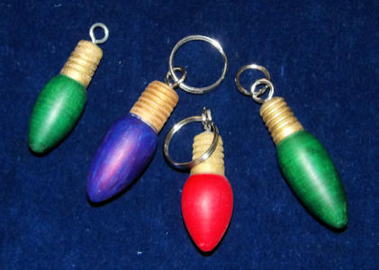
(click above for close up view)
The examples in the above photo show that the RH green bulb is probably too long
for its width.
It doesn't have to be a plain colour. Paul had inherited some glitter paint from
a past Member which he applied to a second bulb. This was not only the
first time he had demonstrated glittery decorations but also the first time he
had ever used it, so we all learnt together that it needed to be thoroughly
shaken before use and that it was best to brush on fairly thickly as the
supporting clear varnish did a good job of smoothing the finish. Paul did
wonder if a coloured base coat might be beneficial the next time he made one.
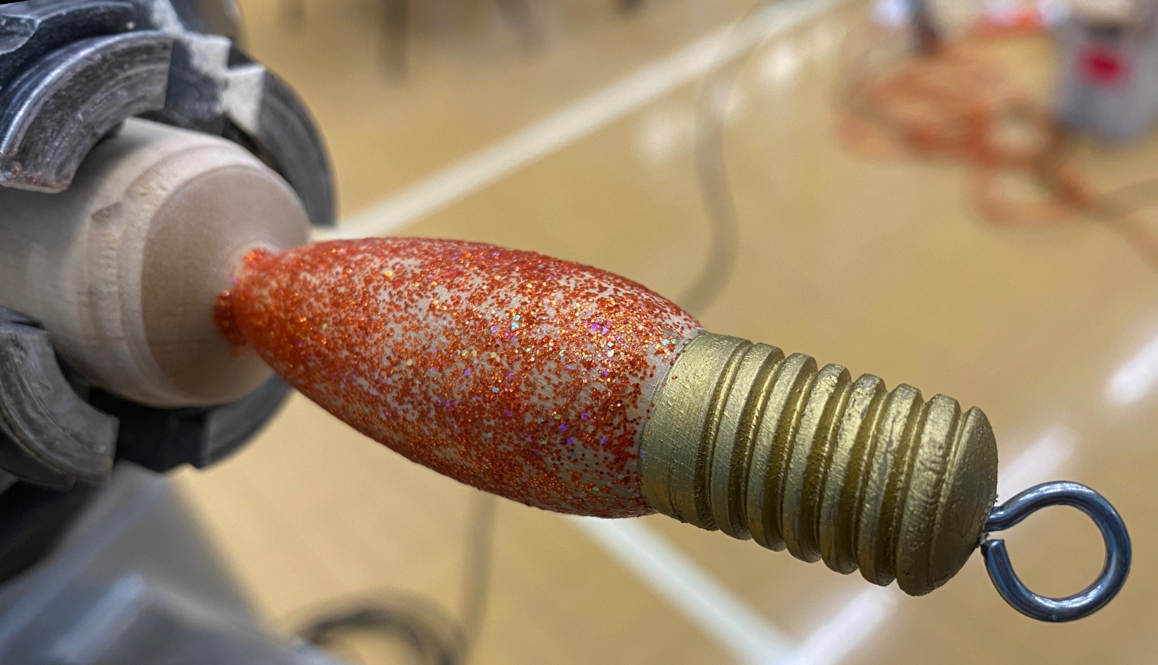
(photos by Andy Ogilvie)
<to
top>
October 2023
Toothpick
Holder with
Paul Reeves
Thu 19th Oct at MWCC Club Night
The majority of turned items tend to be from a single piece.
However, a Toothpick Holder requires turning several individual components which all have
to fit within each other, i.e. the knob, lid, caddy and body, which makes
for an interesting and rewarding project and arguably one that becomes more
relevant as we and our teeth age! One doesn't even have to worry about
food safe finishes.
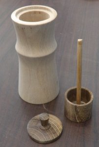
The design of the holder is such that the lid rests loosely on a lip and
attached via a dowel to the caddy, which must be able to slide smoothly up and
down within the body.
To drill holes in wood (particularly deep holes) it is preferable to use a drill
rather than a box cutter to achieve the straight parallel sides required.
Even though hole cutting should be done at a slow lathe speed, it will inevitably
warm up the wood, so it is preferable to drill before turning away the outside
of the component because a thicker wall will be able to dissipate heat better
and less likely to split than might a thinner one.
Consequently, Paul prefers to start with the innermost cut and then turn away
its outside to fit the next holed component.
With that said, there are many turners who favour working from outside to
inside. The choice is yours.
From experience of previous holders he has turned, Paul had planned a
cylindrical blank for the body capable to accommodate his 32mm Forstner bit but
still leave sufficient side thickness to fashion some shape to the outside.
Most 'YouTube' examples show the knob and lid created separately, whereas
Paul prefers to turn these from a single blank. This method might well
create more wastage but if the body, lid and knob have a marked grain/spalting,
the end result will be much improved with all 3 parts matching and aligned.
Paul's lid had to be a diameter of a few mm greater than the 32mm hole so
it wouldn't fall in and able to accommodate at least 20mm depth for lid & knob
combined.
The caddy (ideally a piece of dry stable close-grained wood) needed to be
cylindrical blank wider than the 32mm so it could be turned down to fit, and be
able to accommodate his 25mm Forstner bit. The inside depth of the caddy should be about 25mm; if it was a bit more,
by the time one had added a 5mm base, the caddy tended to look out of proportion.
The diameter of his dowel proved to be too big for his 4.5mm drill bit but too
loose for a 5mm hole. However, he chose to go for the smaller drill
because despite tailstock and headstock supposedly being in line, inevitably the
drill bit held in a Jacob's chuck and the wood held in the headstock chuck will
introduce minute disparities that will result in the 4.5mm drill creating a
marginally larger hole because it was ever so slightly off-centre.
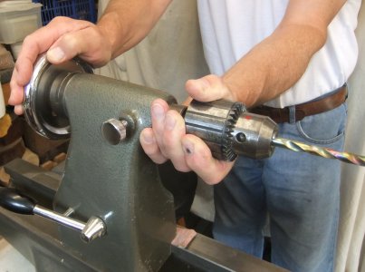
Top Tip
: When using a Jacobs Chuck, the
operation works well while under the positive pressure of winding the drill into
the piece, but upon withdrawing, the bit can bind onto the inside of the cut hole
and get pulled out of the morse taper.
Suddenly, a perfectly still drill chuck
with gear teeth has started revolving at the speed of the lathe.
Anticipate this
by supporting the chuck to stay in the tailstock with your free hand gripping it
clear of the gear teeth.
The Lid
Paul had chosen a piece of Laburnum (for it's stability, strength and finish)
and mounted it in his chuck. With his Jacobs Chuck in the tailstock, he
drilled a hole about 5mm deep for where the dowel would eventually be glued.
This end was to be the underside of the lid. With the Jacobs being replaced with
a revolving centre, the piece was well supported for turning to a cylinder and
squaring off the end carefully with a skew so as to not press the skew's edge
hard against the tail centre. The end 5mm or so was turned accurately with the aid of
callipers and a parting tool to 36mm then slightly tapered towards the tail
stock so as to help the finished lid to drop into position when it's let go. Then allowing
this worked 5mm to remain at
the tail stock end, he turned away the rest to fashion a knob - he chose a
dovetail shape. An advantage of using a wood like Laburnum was that it is so
close grained and strong that a small parting tool can produce smooth accurate
shaping. Before parting off, the piece was sanded.
The Caddy
Paul had selected a piece of 'Pride of India' aka Golden Rain Tree (Botanical
Name: Koelreuteria Paniculata) confusingly from China. He hadn't used it
before but it was purported to behave like Boxwood so should be ideal for this
job.
Having been mounted in his chuck, the procedure was similar to above other than
he used his 25mm Forstner first to cut about 25mm deep and then changed to his
dowel sized drill to drill a further 10mm. He removed the Jacobs; accurately
measured the internal depth for determining where the base would be and replaced
with a revolving centre to steady the piece for turning the 'fit-critical'
outside. (Should one/both ends of the caddy be a sloppy
fit inside the length of the body, there is a likelihood that the caddy will
tilt away from level as it moves up/down and jam its leading and diagonally
opposite edges against the inside).
With the piece supported between chuck and tail centre, Paul carefully and
gradually turned the outer surface down to 31mm diameter with the aid of
callipers and small parting tool, which worked perfectly provided the tool is
kept in motion back or forth.
(Whenever working with a wood type for your first time,
it is important to check regularly that the tool you're using is working as you
want, especially when using abrasives; eg sanding Yew too vigorously leads to
overheating and cracks in the finished surface whereas light sanding with rests
in between grits works fine).
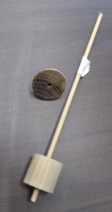 The tail centre was removed so Paul could chamfer the inside edge of the
opening. To compensate for the missing tail support, he rested a couple of
fingers of his tool rest hand on top of the turning piece. As the piece
turns down onto the cutting edge of the tool, its natural reaction is to climb
upwards but the steadying weight applied by his fingers dampens the vibrations,
which would otherwise cause an uneven finish.
The tail centre was removed so Paul could chamfer the inside edge of the
opening. To compensate for the missing tail support, he rested a couple of
fingers of his tool rest hand on top of the turning piece. As the piece
turns down onto the cutting edge of the tool, its natural reaction is to climb
upwards but the steadying weight applied by his fingers dampens the vibrations,
which would otherwise cause an uneven finish.
Light abrasives were used to flatten the surface before parting off at the
pre-measured depth plus say 5mm for thickness of base. This time, because of the
central hole drilled for the dowel, Paul could part off exactly on the
calculated line without worrying that the final cut would pull out some end
grain. The bottom was finished with sanding by hand.
Assembly
Bearing in mind that most commercial toothpicks/cocktail sticks can vary from 50-85mm; that the lid
is of about 5mm thickness; the caddy base is another 5mm and one will need some
space to pick, lift up and clear the caddy to remove (say another 5mm); it
follows that the hole depth in the body should be a minimum of 15mm plus the
length of your stick. Paul had sticks of 80mm so used 95mm as his minimum figure.
Paul glued one end of the dowel into the lid and allowed it to dry before the dowel
was sawn off 95mm below the underside of the lid and glued into the pre-drilled
hole in the base of the caddy.
The Body
A 40mm cylinder of spalted Silver Birch had been prepared with its end trued off
for mounting into the Club's chuck and a Jacobs chuck with his 32mm Forstner
drill bit in the tail stock. Paul stuck some insulation tape around the stem of
the drill bit at 95mm from the bottom of the cutting edge (which is
flat with a Forstner but often cone shaped with other wood drills which will
thus need additional depth to compensate).
Remembering the TopTip above, Paul reduced the lathe speed and keeping his
fingers gripping behind the gear teeth, drilled until the tape marked depth
reached the entrance hole. While drilling this amount of depth, he found he needed to withdraw the
bit to clear the shavings 3 or 4 times during the procedure.
He then swapped the Jacobs with a large diameter tailstock revolving centre to
steady the piece for shaping the outside.
Paul opted to create a gentle upward slope to where the lid would sit.
With the tail centre temporarily removed, he gradually turned a chamfered edge
within a few mm of the opening that matched the chamfer of the lid. With regular
checks to see how the lid rested in position, he decided upon leaving the lid
slightly above the body's edge. If the dowel had been left too long, one
could still shorten it before gluing it to the bottom of the caddy.
He chose to shape the sides with 2 coves using a smaller one at the top for
aesthetic proportion.
Spalted wood has areas of different colours which have different
densities that will wear down at different rates resulting in an uneven
surface. Treating the surface with sander sealer will help to reduce the
softer areas abrading away quicker than the denser areas.
With soft/spalted woods, 400 grit is about as far as you should dare whereas
with hardwoods, one could continue down to much finer grits.
Having re-checked the actual internal depth of the body and adding at least 5mm,
Paul marked the intended base of the body and proceeded to part off clear of the
mark because a parting tool will inevitably tear out when cutting end-grain.
He finished with quickly turning a jamb chuck so that he could reverse the
piece, finish off the base with a Skew and/or abrasives and even contemplate
some decoration.
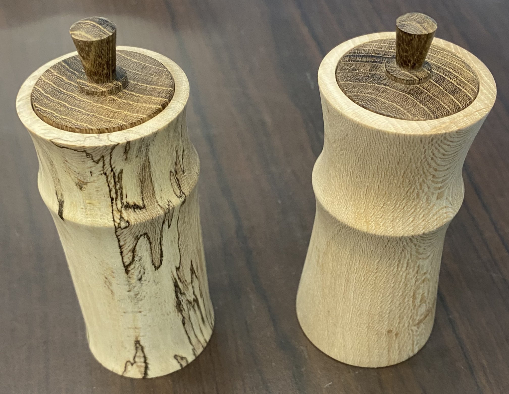
(photos by Rick
Patrick & Paul Reeves)
<to
top>
September 2023 -
DEMO 4
 Decorative
Mushrooms
with
Paul Reeves
Decorative
Mushrooms
with
Paul Reeves
Thu 21st Sep at MWCC Club Night
Turning a mushroom is a perfect use for branch wood. Few projects can
so readily integrate bark, sap, heart and pith in a single piece. It
doesn't even matter if the piece cracks, splits, withers or weathers with age,
it will still look realistic.
Ideally, choose a wood with contrasting colours within its grain - although last
month's
Splash of Colour demonstration
could be incorporated when using a bland coloured wood to produced those
red-topped white-dotted examples.
A popular choice is Yew but Paul had brought a selection of more exotic branch
wood including Giant Redwood (Sequoia), Judas Tree, Juniper and Japanese Maple
as the example of a bland wood.
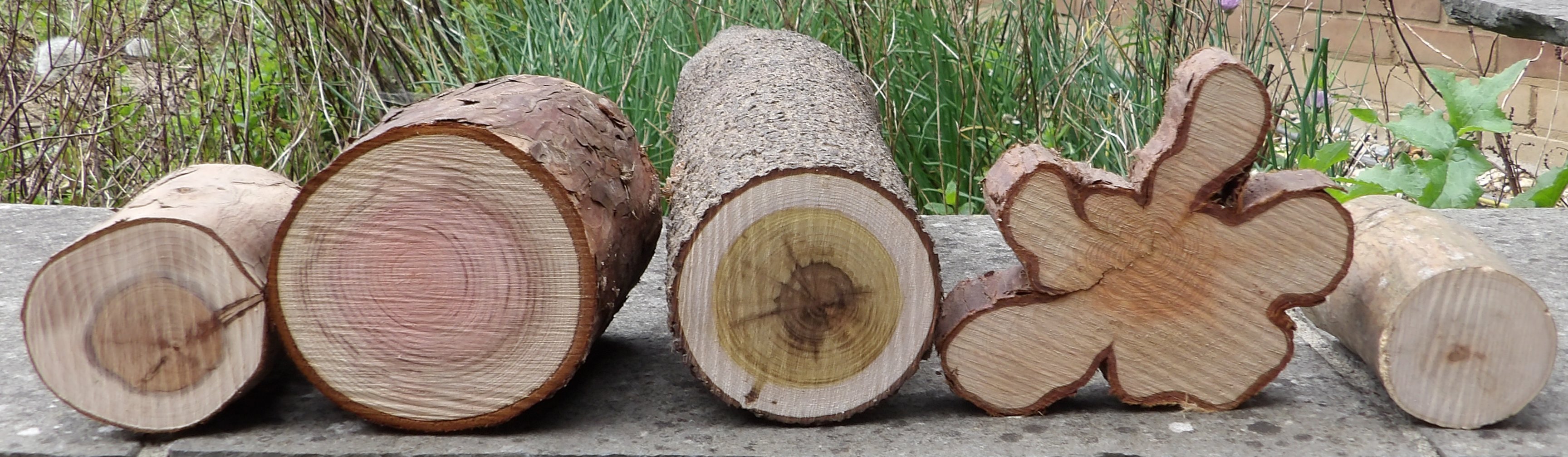
(All pictures
with a blue border can be clicked for a closer view)
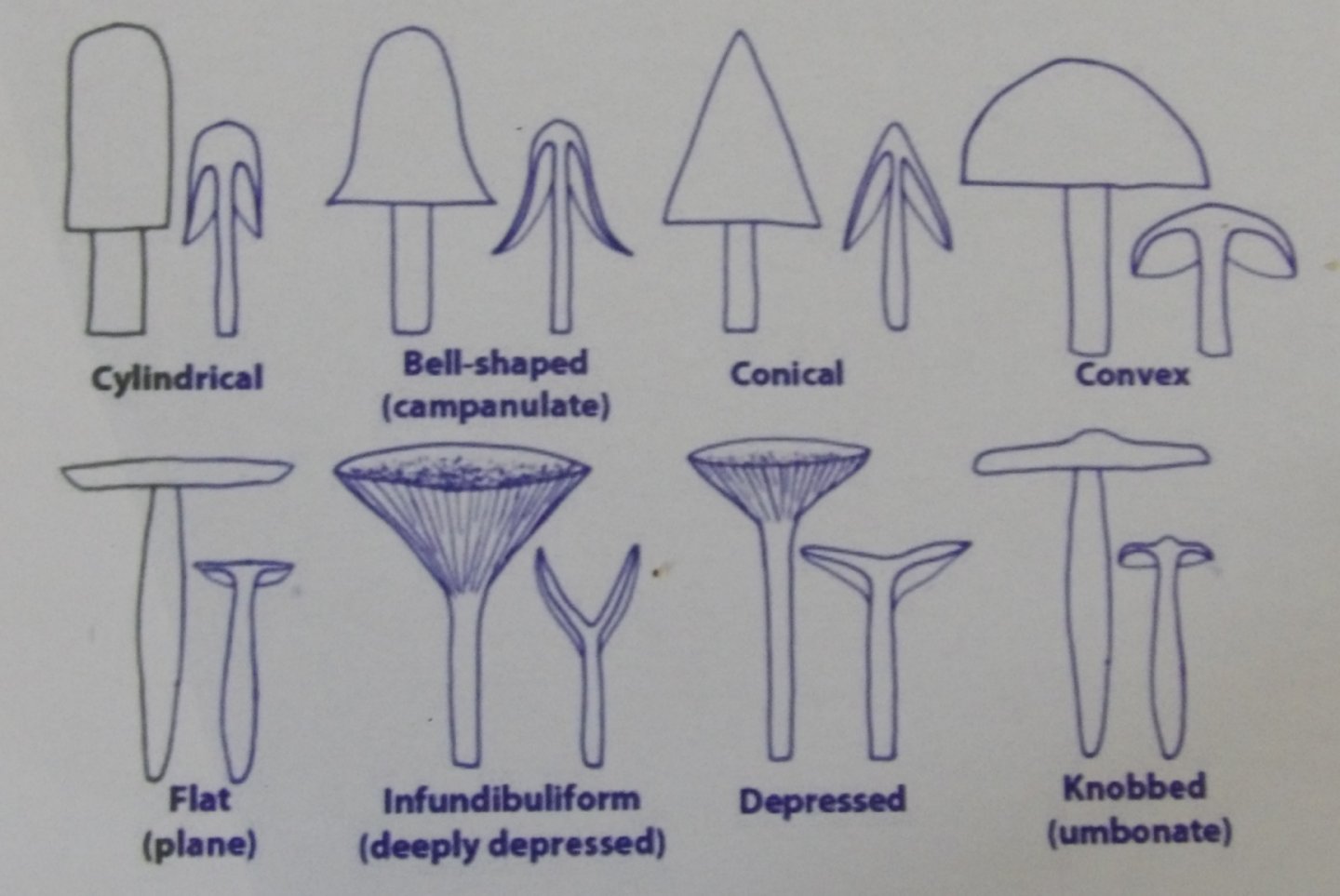
1. Shapes
Mushrooms have quite a selection as illustrated to the right.
Turning is ideal with wet wood but note that most of the taller caps have deep
undercutting underneath, which is helpful in avoiding cracks/splits to appear
over time while drying.
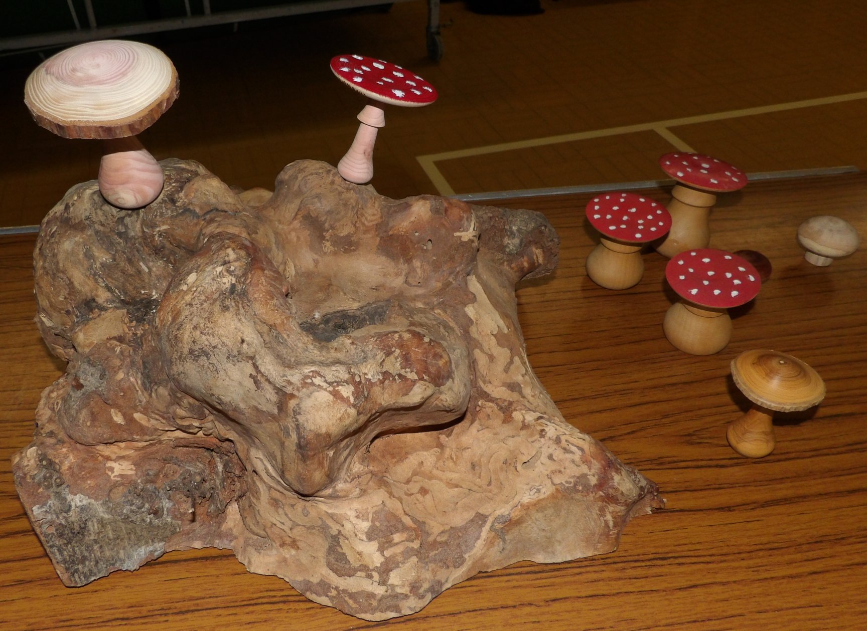 2. Presentation
Solitary
pieces are the norm but to make an impression, try turning a group displayed on
a natural looking base, eg rotted or burred wood or a base covered in moss.
Mushrooms never stand precisely straight in real life so if turning a solitary
example, it looks better if you saw/sand a bit off the base to produce an
off-perpendicular piece. With a group displayed on a base, the pieces were
all turned with a 8mm spigot so that an 8mm drill could be drilled
anywhere on your show base and at any jaunty angle of your choosing.
3. Tools
A Spindle Gouge could do everything but it is easier for smaller sized tools
like thin/curved scrapers and hollowing tools for
undercutting the deeper caps.
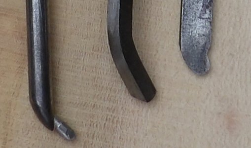
Giant Redwood - Paul had mounted a piece of Redwood
between centres with the chosen end to be the cap placed against the drive
centre.
A Roughing Gouge was used to turn a cylinder from the tail end to about halfway.
Using a Skew Chisel, he turned a V-cut such that the left hand side remained
clear of the drive centre's edges and the right hand side starting to form the
shape of the chosen cap top while leaving a small stub for the drive centre to
continue spinning the piece.
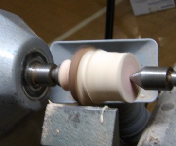
Then with a Spindle Gouge, he continued shaping
the stem/stalk. If the piece is to be free standing, leave the base more
bulbous in order to lower the centre of gravity and improve stability.
Paul preferred to have his stem running thinner towards the cap and (depending
upon the wood) arranged to leave a bunched-up curved shaving just below the
underside of the cap to mimic the ring/skirt often found on a mushroom. This
annular skirt is the remnants of a sack-like veil originally connected to the
edge/margin of the cap prior to the mushroom starting to grow out of the ground.
He then repositioned his tool rest at right angles to the stem in order to
better support his gouge as he turned away the underside of the cap to
approximately parallel of the intended topside. He took care to avoid
damaging the bark remaining on the edge of the cap.
Continuing with his Spindle Gouge, he
continued with the cap's top surface without cutting it completely off.
He sanded all round with 180 grit only, commenting that real mushrooms tend to
have matt finishes.
Returning to his Skew Chisel, which works perfectly for cutting across the
grain, he turned off as much as he dared (about 5mm spigot).
Now it was decision time for parting off the base.
For standing alone pieces - saw off the base at an angle remembering to back off
the tailstock to reduce the squeezing pressure on the piece;
For mounting pieces on a base - while still between centres, create an 8mm spigot
before parting off.
Finally, the top was sawn off and sanded smooth.
4. Decorative
Options
PYROGRAPHY - The underside of the cap often has gills which can be
replicated by scorching with a carving blade iron. Once brought up to
temperature, drag the nib outwards towards close to the edge. Slower movements
produce darker & wider marks - if too dark, try brushing off with a toothbrush.
An alternative is a Dremel fitted with a disc cutter and then scorch with a blow
torch.
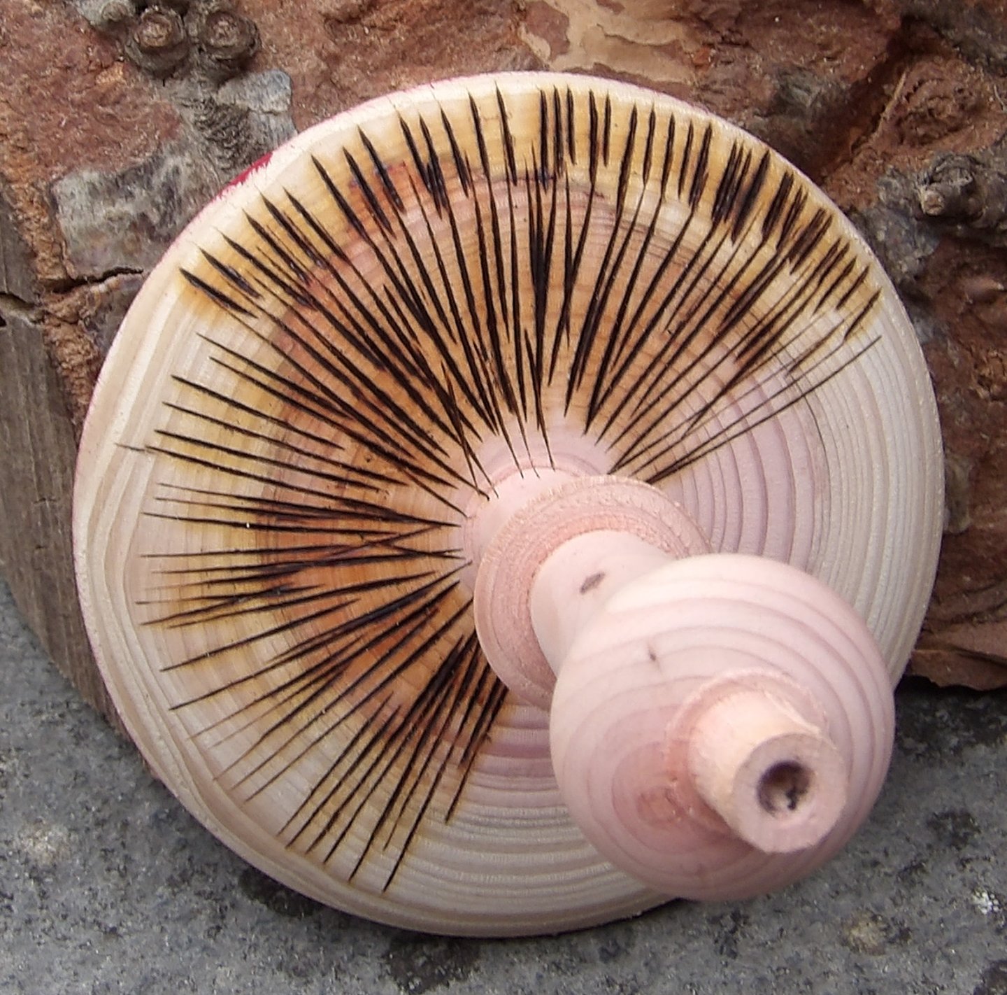
ACRYLIC PAINTS - Ideal for decorating plain woods with a brush or cloth. Drying time can be shortened with a hairdryer. Acrylic paste is a good way of creating a protruding white spot/scale over a red background.
WOOD STAINS - Another option to suit plain woods. See Splash of Colour demonstration for technique.
Button Mushrooms -
Although smaller overall, these mushrooms have comparatively thicker stems but
will still need a smaller drive centre than used above. Procedure much as
before other than Roughing Gouge removes all the bark and the smaller size led
to Paul turning 2 mushrooms from a single piece with a cap turned at either end.
Additionally, he used 240 grit all round to produce a shinier finish like the
real Button Mushrooms and he used a thin Parting Tool close to the stem for his
undercut.
These are prime candidates for plain coloured wood and wood stains.
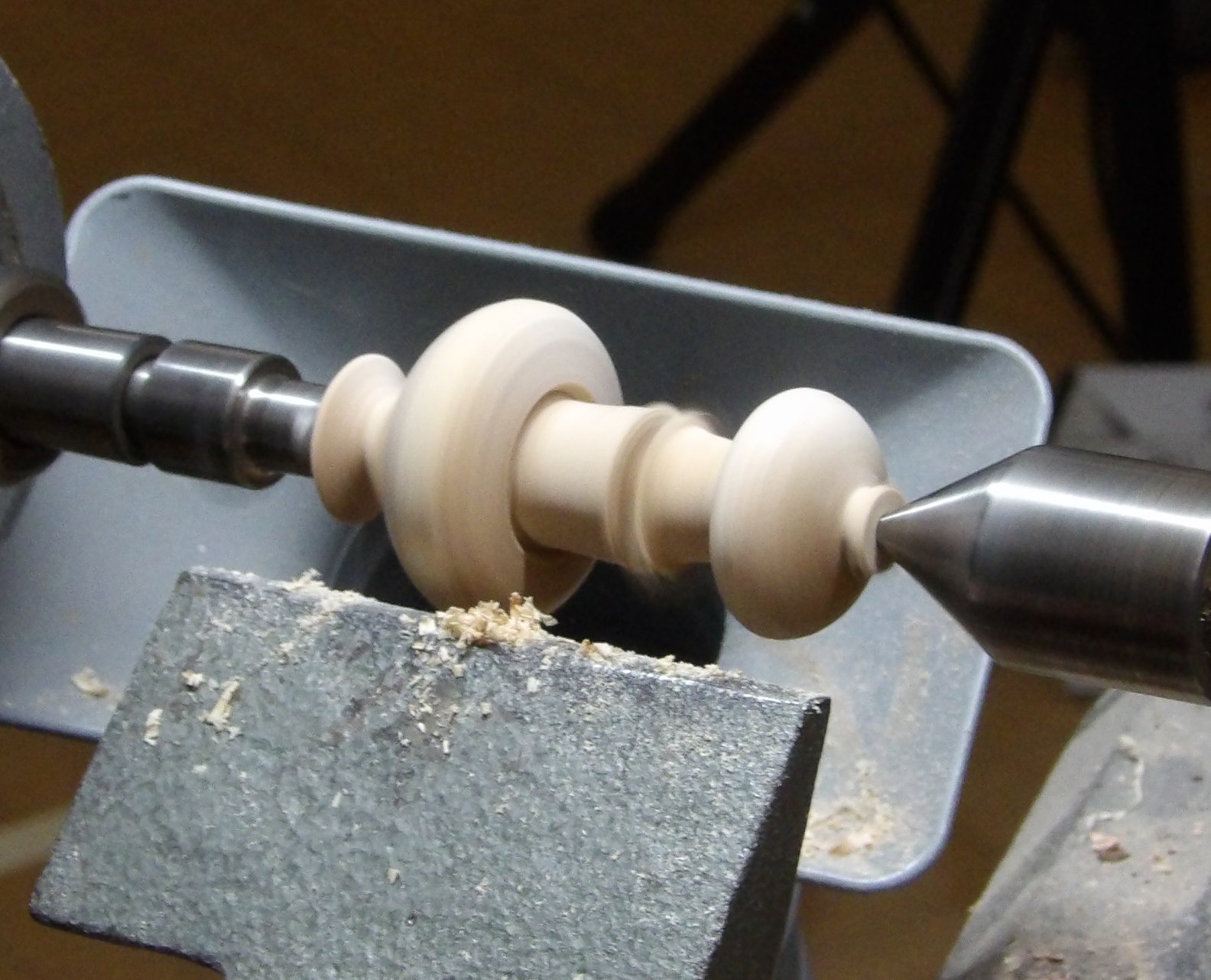
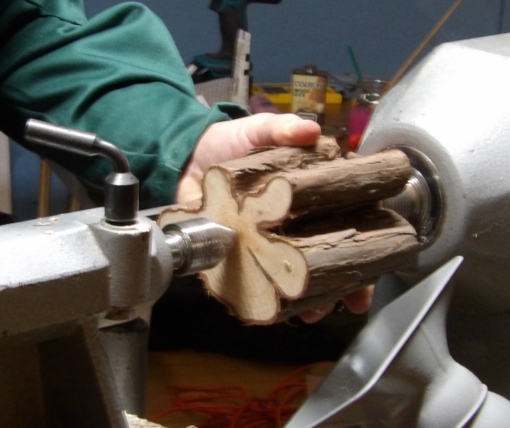
Lobed Mushrooms - Paul had a piece of Juniper between centres, not necessarily on the pith but rather a point chosen equidistant from the various inward folds. One might think to be wary of the piece being out of balance but with such a size as small as tonight's pieces, there won't be any danger of the lathe walking itself across the workshop. Paul recommended that we treat it as a normal piece; in fact, high speed is your friend with odd shapes because the gaps pass quicker and your gouge is into cutting again with minimal deflection.
The finished Demonstration pieces
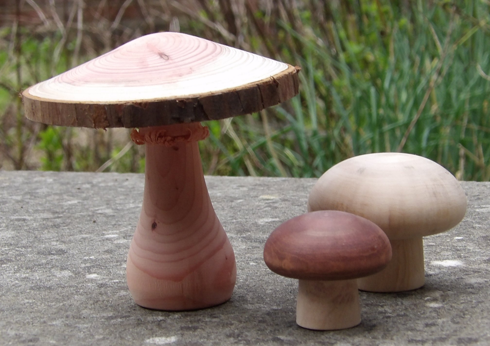
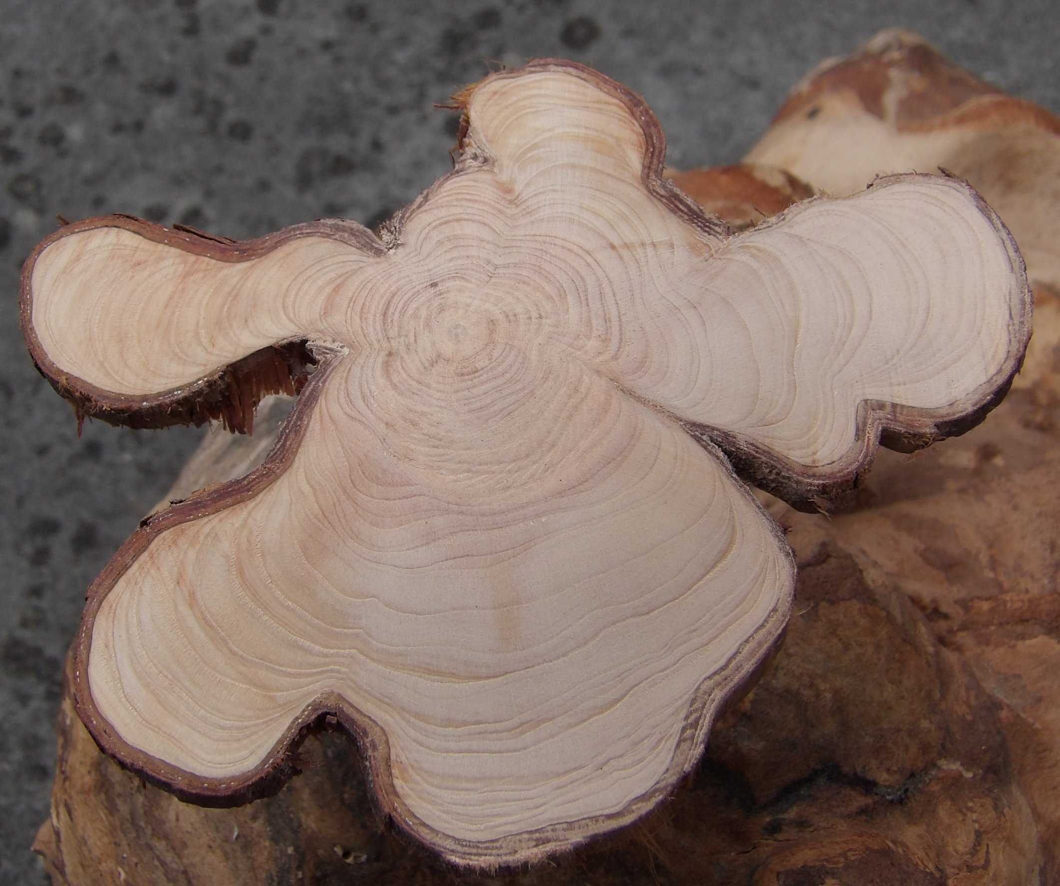
5. Other Ideas
A popular request from family & friends is a Tooth Fairy's Mushroom,
which has the stem fashioned as a box to hold the tooth overnight but magically
changes to a coin by morning time. It is recommended that the box is not
made big enough to hold a £2 coin inside!
Below is an example from Pinterest of a downlighter mushroom; the
reflection reveals a strip of LED lights embedded into the underside of the cap
that are powered by batteries secreted within the stem.

The October Competition was set to produce turned mushroom(s) incorporating a decorative feature.
(photos by Andy Ogilvie, Rick
Patrick & Paul Reeves)
<to
top>
August 2023 -
DEMO
3
A
Splash of Colour
with
Paul Reeves
Thu 17th August at MWCC Club Night
Paul started the evening asking how many of those present had used colour in their
wood turning - (about 10%).
Then he asked how many liked to see colouring in wood
turned pieces - (again, about 10%)
This response validates Les Thorne's comments to the Club earlier this year that
he had stopped demonstrating various colour techniques due to a general lack of
interest.
Paul admitted he wasn't a fan of colouring for the sake of it but did believe
there were 3 occasions when colouring could enhance the finished piece :-
1. Spot Colouring
2. Liming Wax/Gilt Creams
3. Spirit Staining
Spot Colouring
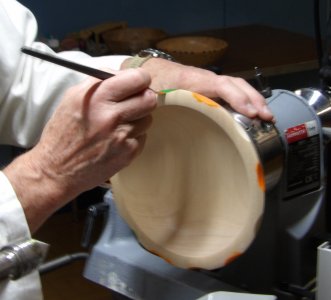 Small
subtle areas of eye-catching colour(s) can emphasize an edge or boundaries of a
decoration on an otherwise bland blank.
Small
subtle areas of eye-catching colour(s) can emphasize an edge or boundaries of a
decoration on an otherwise bland blank.
As an example, Paul had prepared a pale Sycamore bowl which he proposed to lift
its plainness by adding some colour to the outer edge of the bowl's rim. To
create a surface to show off the paint, he had used the indexing facility on his
lathe to mark out 12 symmetrical points around the edge. Using a drum
sander with 120 grit mounted into his chuck, he just pressed the bowl edge into
the spinning sander to make a lozenge shaped indent. (Similar effects could
be achieved with the bowl mounted in the chuck and using a Dremel with a drum
sander or other attachments).
Although the centre marks had been precisely drawn, Paul believes to use even
pressure and movement by hand & eye to generate the indents so that the slight
variations in size and depth underscores one's hand-made craftsmanship.
As Sycamore is very pale, Paul had chosen bright contrasting colours of green
and orange.
There is no necessity to spend a lot of money on paints as there are many
discount shops (Lidl, InXcess, Milford Supplies) that sell an array of
acrylic paint pots.
TOP TIP
: To keep painted edges sharp and to help remove any
paint overspills, apply a sealer first as this will close up the timber pores
and provide a solid foundation for the paint. Any overspills can be wiped away
while wet or sanded away with 400 grit once dry.
He brushed on his paint keeping the paint thickness even and of alternating
colours. He carefully wiped away any paint that had settled in the wrong place
with a cloth before allowing it to dry completely - quickened with a combination
of lathe turning and a hairdryer.
He used fine abrasive along the grain to leave crisp edges of colour and finally
600 grit before tack ragging and a spray Cellulose sander sealer to seal in the
colour.
Paul had also experimented with staggered bevelling on both inside and outside edges of a bowl with an intention to paint the resulting upwardly facing wiggly line.
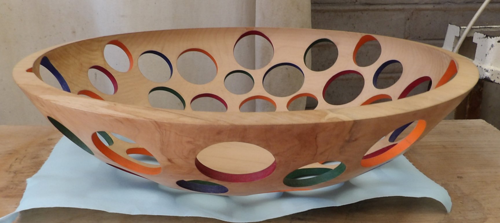
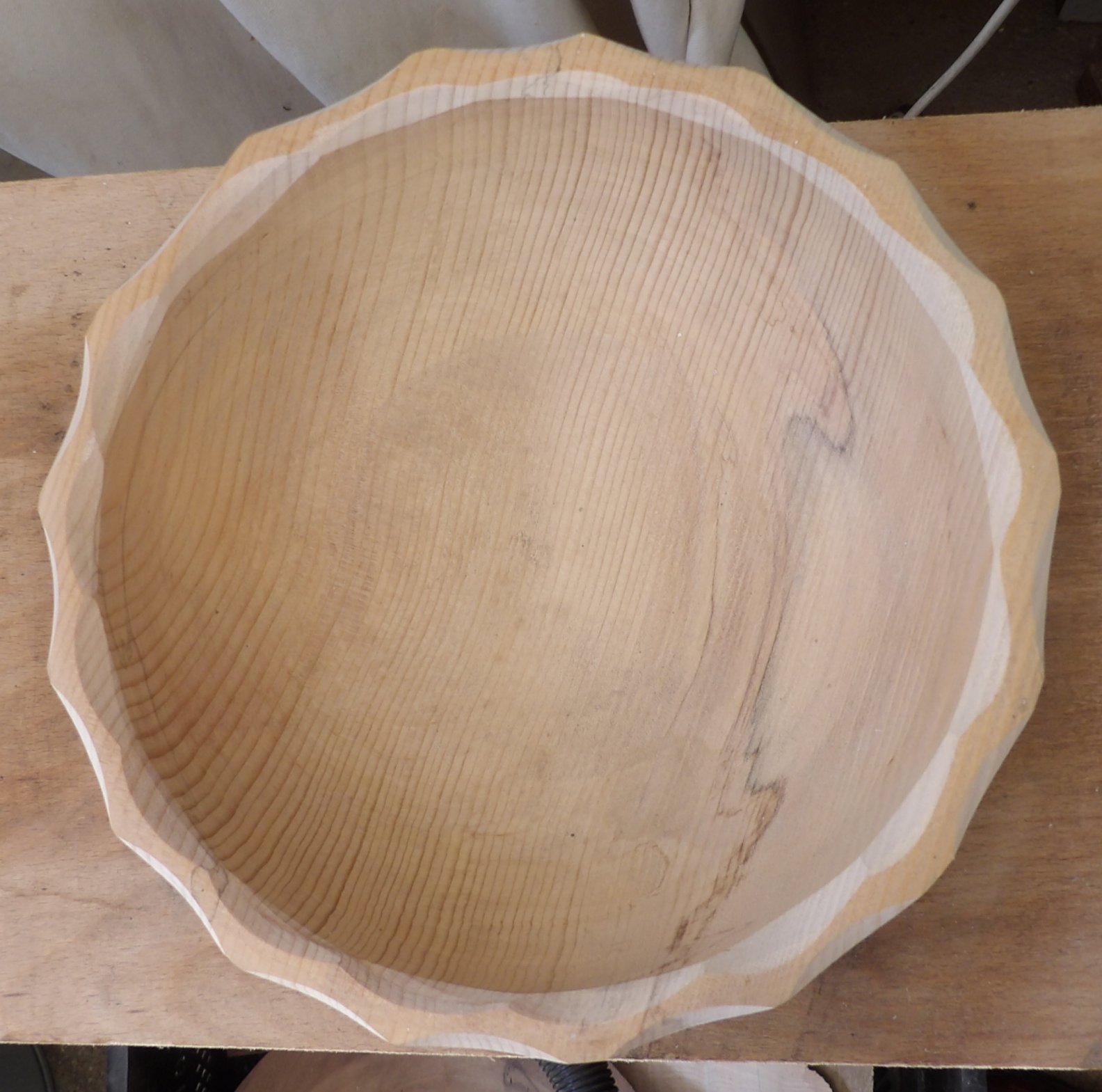
(click either above for close up view)
Liming Wax/Gilt Creams
These are designed to work their way into the grain of the wood to make them
stand out in a striking manner. They are particularly effective on deeply
grained ring-porous timber (eg Oak, Ash) where the pigmented wax can settle into
the grooves, accentuating the grain and adding a sense of depth and texture
often resulting in an enhanced rustic, antique feel.
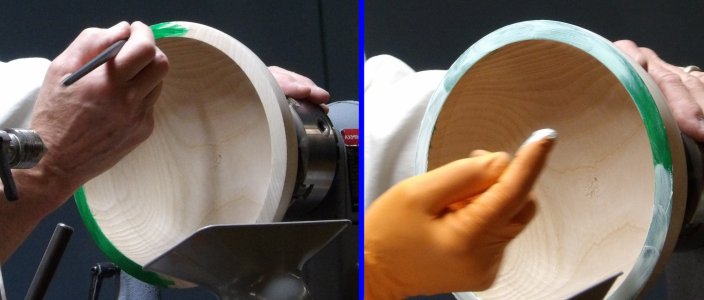 Paul
had prepared a plain Ash bowl having a flattened rim with prominent grain.
After sanding and sealing, he applied a coloured acrylic paint as above.
Once dry, he used 400 grit to open up the wood pores again and used a soft brush
and tack rags to remove the dust.
Paul
had prepared a plain Ash bowl having a flattened rim with prominent grain.
After sanding and sealing, he applied a coloured acrylic paint as above.
Once dry, he used 400 grit to open up the wood pores again and used a soft brush
and tack rags to remove the dust.
White liming wax was applied into the grain covering the painted rim using a
gloved hand and then he wiped most of it off with a cloth before it was left
aside to dry thoroughly. The instructions on the wax jar talks about using
"finishing oil" but any mineral spirits (eg white spirits) should cure the wax.
Gilt Creams are predominantly available in gold, silver and copper, although
many manufacturers offer numerous shades of each metallic colour as well as
verdigris (green).
These bright/shiny flashes of colour are particularly effective in showing up
grain when the predominant background colour of the piece is very dark or black
from scorching/ebonising sprays.
Application is as with the liming waxes with the exceptions of being sparing
with the gilt (it's more expensive after all) and wiping off the cream with only
fresh unused sections of your rag/paper across the line of the pores to avoid
dragging all the gilt out.
If required, both wax & cream finishes can have added protection with clear gloss/satin lacquer spray.
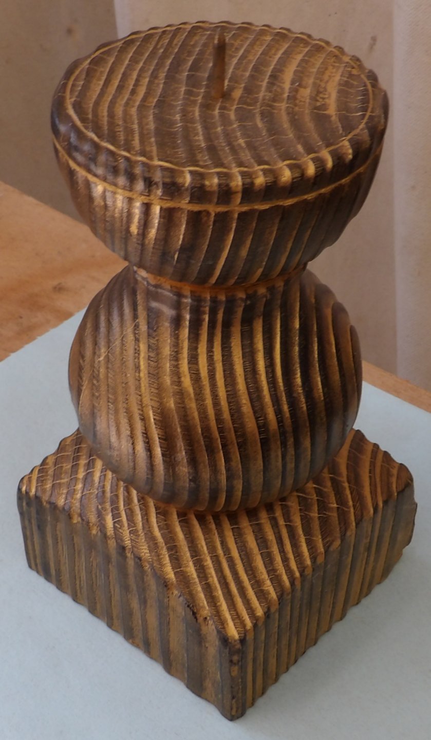
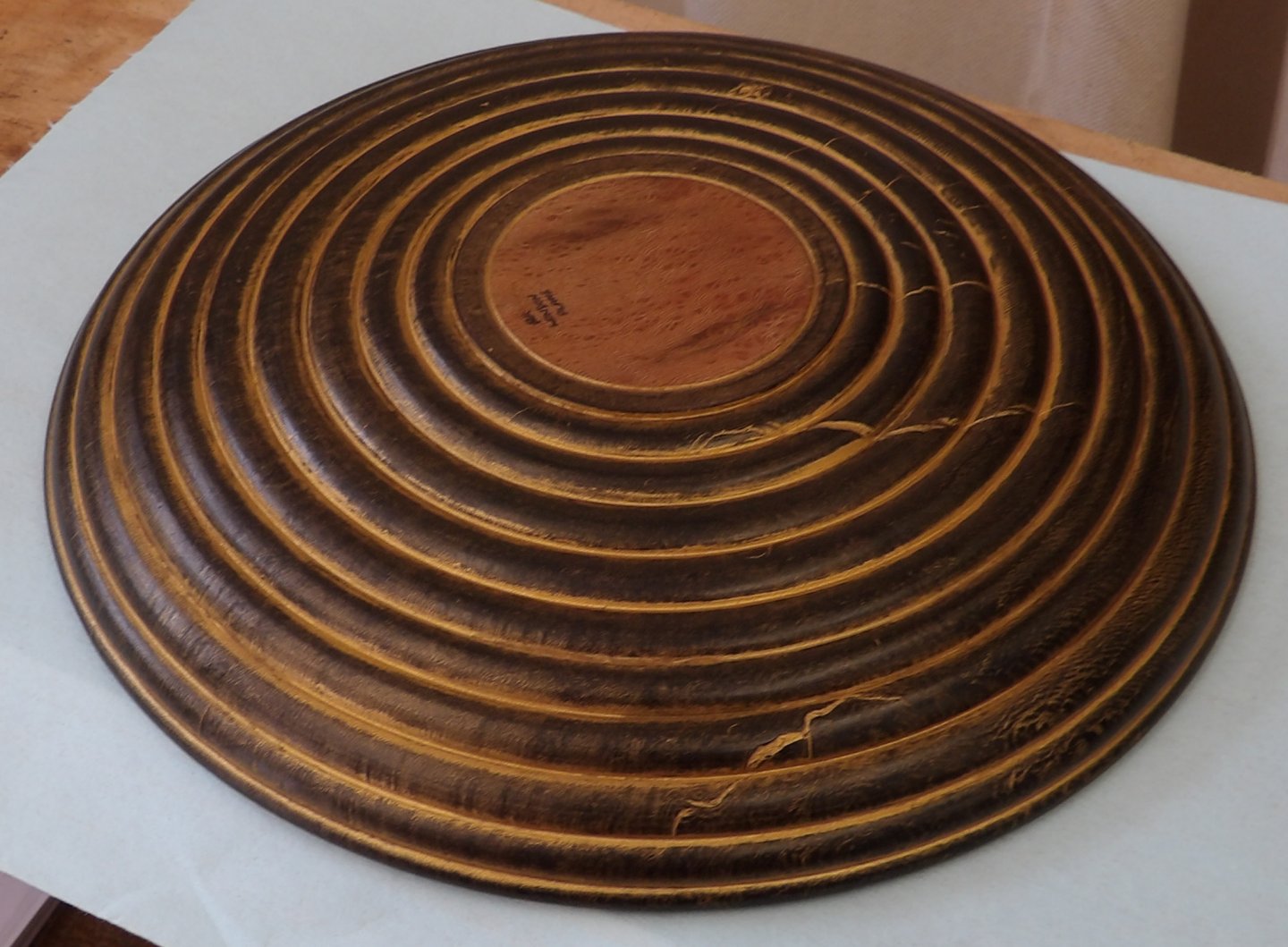
(click either above for close up view)
Spirit Staining
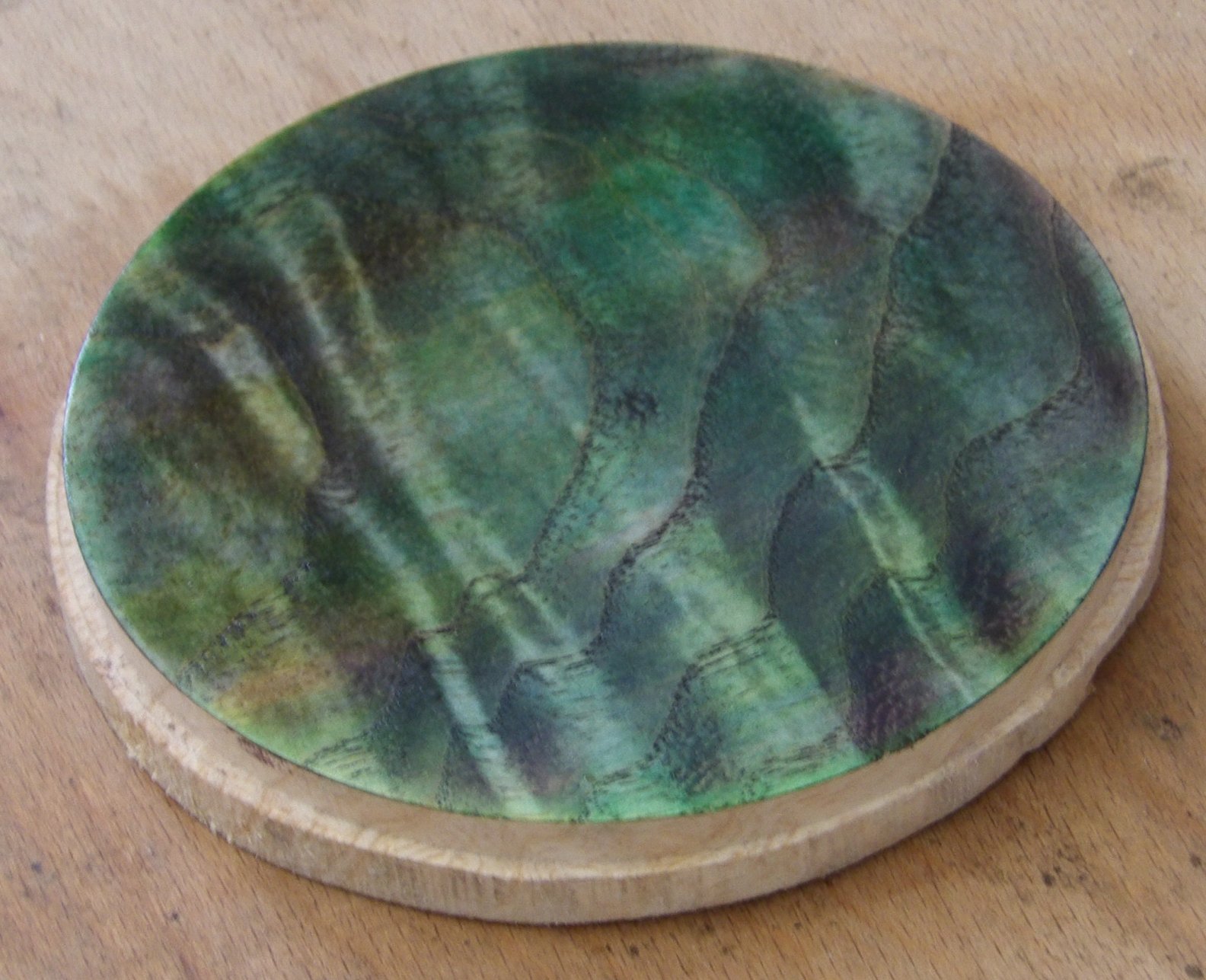 Spirit
stains are remarkably good at bringing out the best in figured wood, but beware,
they are also good at highlighting any tool marks you have left on the surface.
When using abrasives, sand along the grain (which will be across the ripple).
Spirit
stains are remarkably good at bringing out the best in figured wood, but beware,
they are also good at highlighting any tool marks you have left on the surface.
When using abrasives, sand along the grain (which will be across the ripple).
The staining works best when a combination of colours are
selected to complement each other; typically a couple of dark colours applied
first followed by a light colour to produce highlights.
In the wine mat example to the right
A combination of staining and gilt creams is also very
effective.
In the bowl below, Paul had applied several coats of a permanent marker pen
within the decorative band and then sanded it back to reveal where the colour
had soaked into the pores. As the stain doesn't fill up the pores, his
application of Liberon Chantilly Gold gilt cream added a dazzling sparkle.
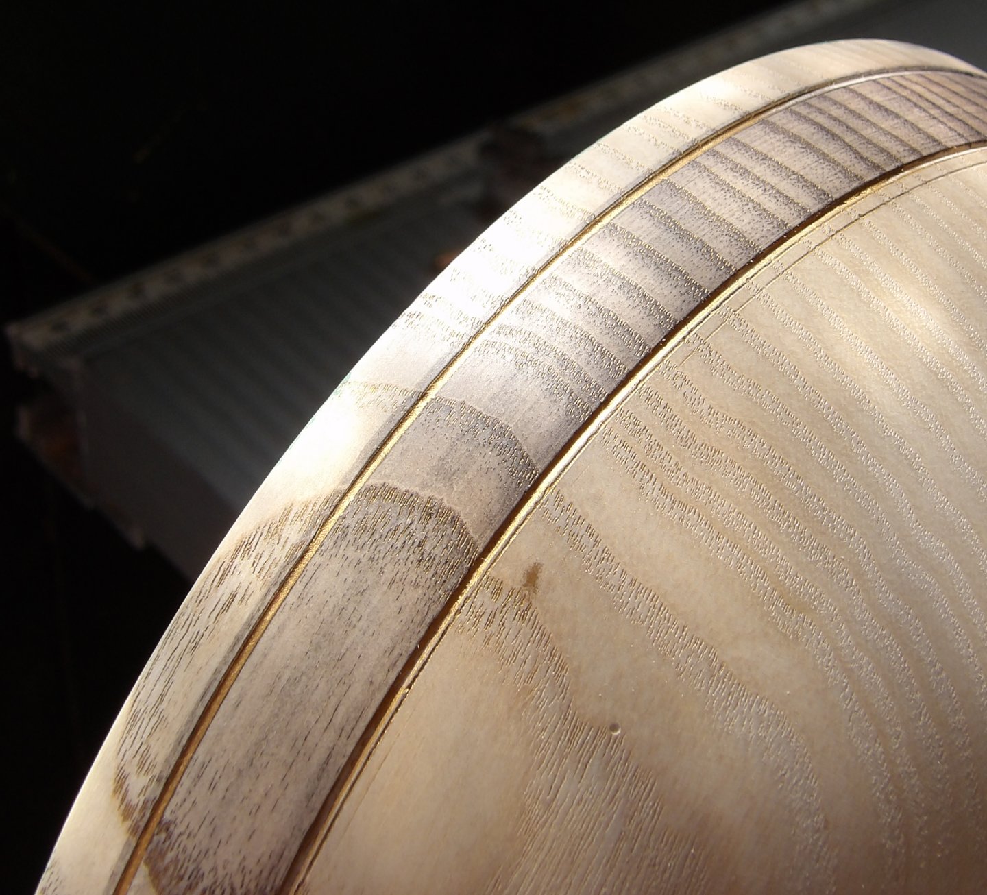
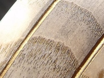
The September Competition was set to produce wood turned item(s) with a splash of
colour.
(photos by Rick Patrick & Paul Reeves)
June 2023 -
DEMO
2
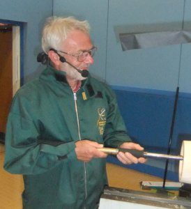 Kitchen
Items
with
Paul Reeves
Kitchen
Items
with
Paul Reeves
Thu 15th June at MWCC Club Night
There are many dozens of examples of utensils, apparatus, gadgets & aids
found in a kitchen.
Paul had brought 20 he had found at home along with examples of blanks he had
taken straight from his bandsaw. He also talked of teapot stands, trivets,
egg stands, mug rack stands, storage jars, cutting boards, biscuit cutters as
other examples.
(click either for close up view)
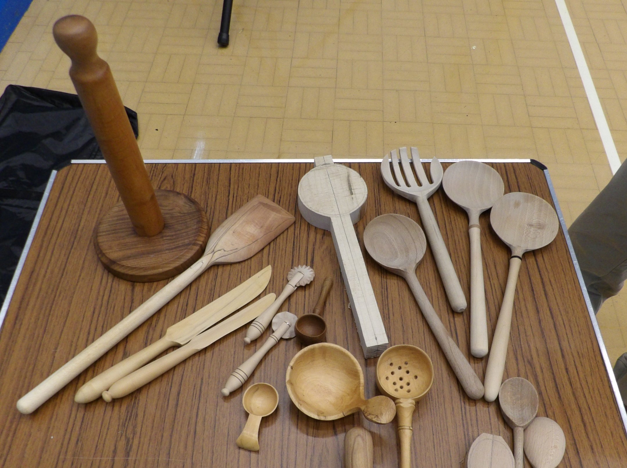
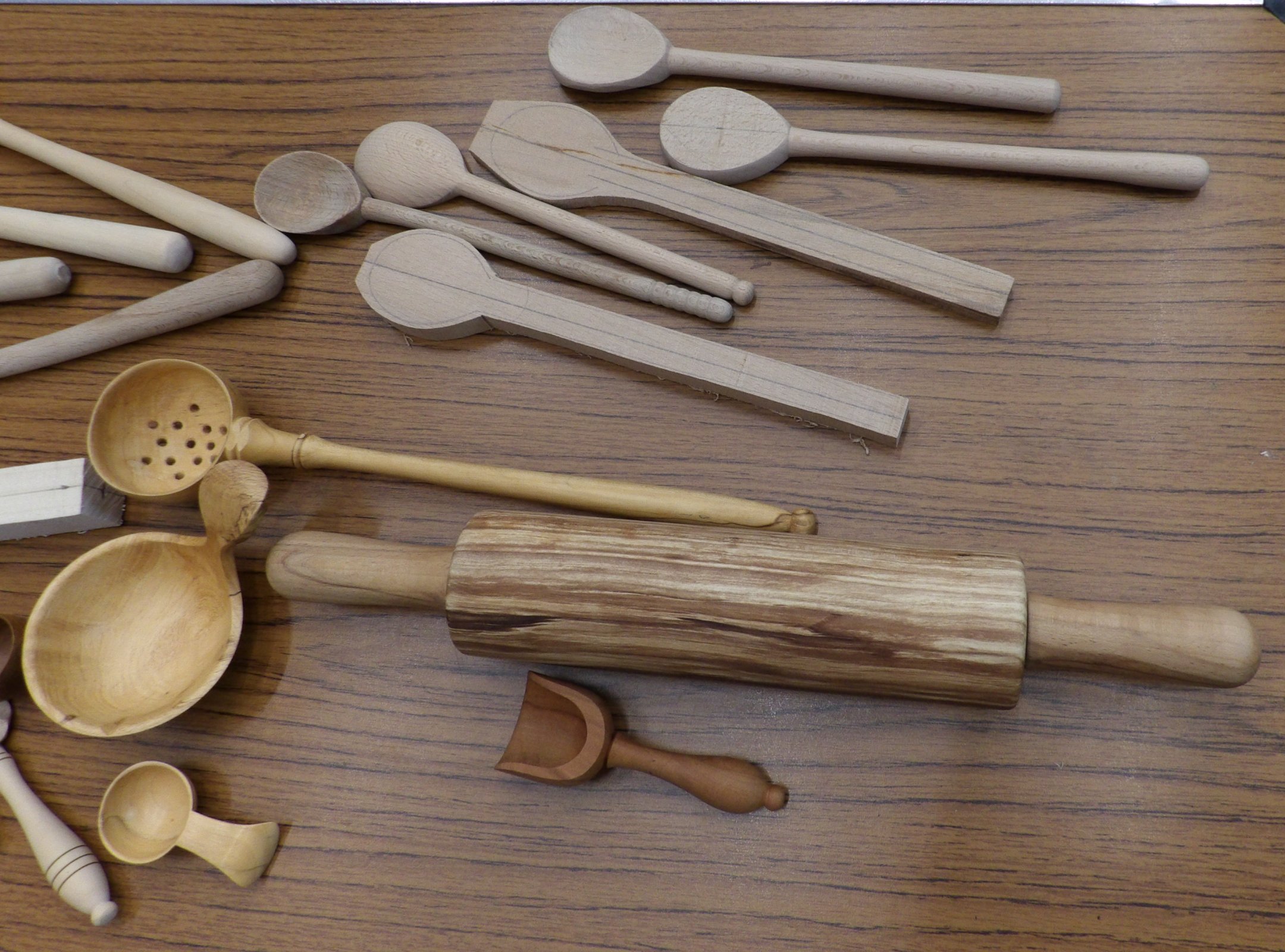
Wooden spoons are an obvious choice but rather off-putting when
you spend hours to produce something that costs less than £1 on the High Street.
However, most kitchenware from a shop is made from Beech so selecting a more
exotic or stunning grained wood can suddenly transform the mundane into
something extraordinary.
Just follow the spirit of the Bauhaus Movement's belief that functional items
don't have to look hideous.
Apart from the kitchen roll holder above, all the other
implements come into contact with foodstuffs.
Most bare woods have some degree of toxicity listed in wood databases. Beech &
Maple are rare exceptions so are most commonly used commercially, but many close
grained woods (e.g. fruit woods, box) would be acceptably safe. A useful habit
to acquire
for food preparers is dipping the wooden utensil in water before using.
It helps resist staining and pore absorption of raw food,
which could otherwise end up rotting beneath the surface.
Paul outlined the various ways of producing scoops, rolling
pins, roll holders & spoons. He warned of ever decreasing cardboard tube
diameters when designing kitchen roll holders and the dangers of turning spoons
out of a single blank. Still perfectly feasible, but needs awareness when
turning the bowl end, because the handle section becomes an invisible
propeller blade ready to thrash the unwary such that even a sadistic
headmaster would wince!
TOP TIP
: On some lathes (particularly if you have rotated the
headstock in order to increase turning clearance) the On/Off switch cannot be
reached as normal so plan how you're going to switch Off BEFORE you switch On.
Alternatively, the danger can be completely avoided by turning a handle (with a
spigot) & a spoon bowl from separate pieces and glue/thread them together afterwards.
Piping Nozzle
(click for close up view)
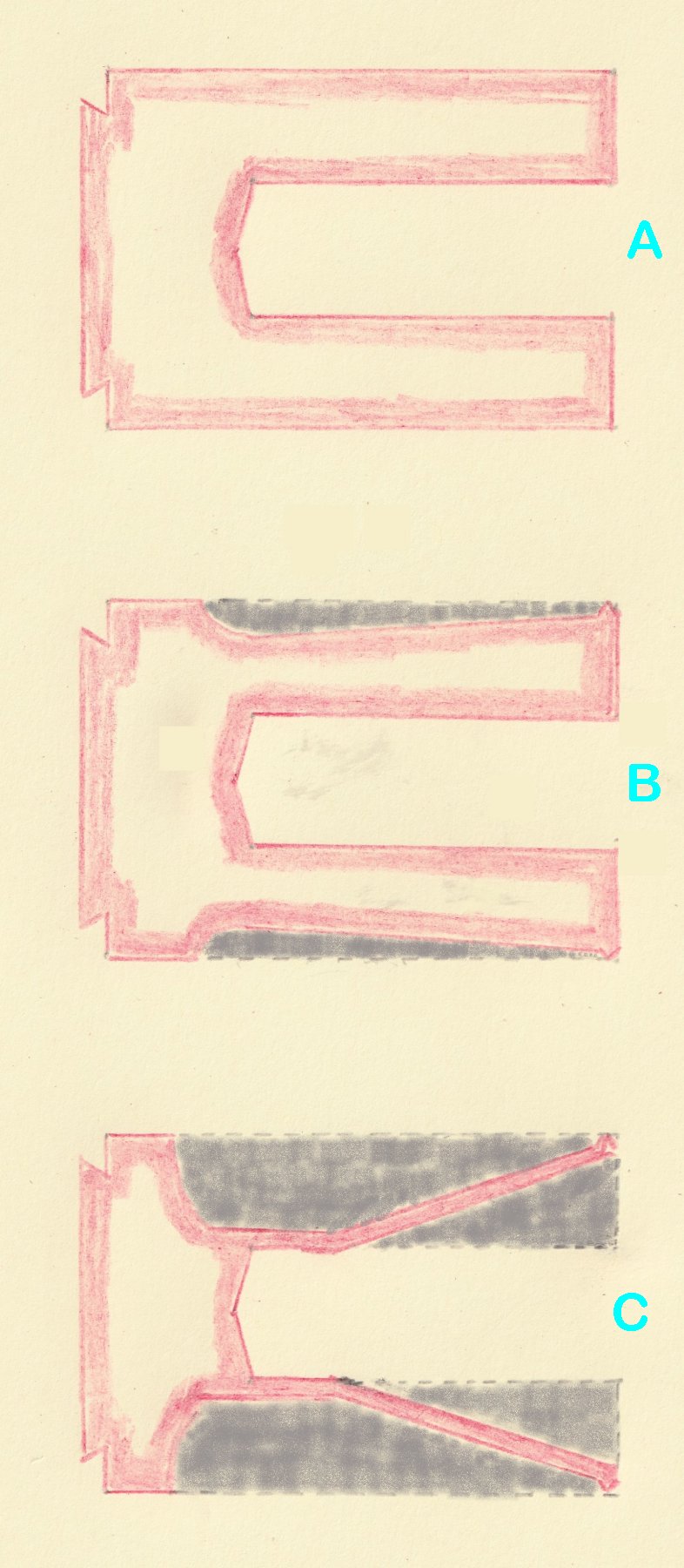
The Roughing Gouge was used to start creating a conical shape but leaving a 2 or 3mm square spigot at the outboard end. This spigot will eventually become a tiny bead that prevents the contents of the piping bag getting past the join between the nozzle and the bag when under pressure. At this stage, Paul just used his Parting Tool at 45º to cut off the two exposed square corners. The job would be finished to a circular bead with the finer abrasives at the end. (Diagram B)
The plan now is to hollow out the centre so that
there is a straight inside edge from a thin wall at the widest point to meet the
central drilled hole at the desired length of the nozzle. (Diagram
C)
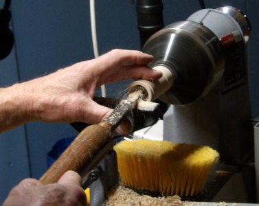 Paul
used a Box Cutter to nibble away the inside of the drilled out opening to a
small depth and to a few mm from the outside edge of the cylinder. When using
this tool, it must be absolutely level.
Working with a Scraper, the handle is invariably higher than the tool rest but
if that happened with a Box Cutter, the hollowing would get wider than intended
as the cutting corner of the tool moved further away from the tool rest.
Paul
used a Box Cutter to nibble away the inside of the drilled out opening to a
small depth and to a few mm from the outside edge of the cylinder. When using
this tool, it must be absolutely level.
Working with a Scraper, the handle is invariably higher than the tool rest but
if that happened with a Box Cutter, the hollowing would get wider than intended
as the cutting corner of the tool moved further away from the tool rest.
He checked the thickness and found the outside diameter (ignoring the bead) was
31mm while the inside was 26mm, making the wall thickness 2½mm. With this Maple,
Paul was happy to take it a bit more off. However, as the wall becomes thinner,
the tendency is for the piece to start vibrating and screech. This was countered
by a lighter bevel touch and supporting the piece with a couple of fingers on
top of the revolving piece.
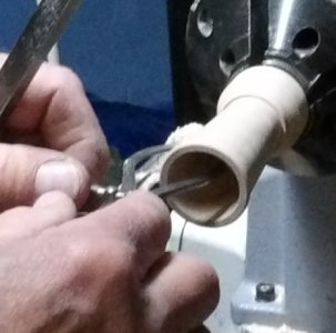 Keeping
in mind the intended length of the nozzle, Paul continued passes with the Box
Cutter to achieve the required straight inside edge. He then worked on the
outside edge by increasing lathe speed and using his Roughing Gouge to remove
waste quickly. He finished with a recently sharpened Parting Tool slightly
tilted on the tool rest so that just the corner was being used. This works like
a Skew but is more controllable. Paul regularly stopped and used Outside Spring
Callipers to ensure the wall thickness was constant over the nozzle's length.
Keeping
in mind the intended length of the nozzle, Paul continued passes with the Box
Cutter to achieve the required straight inside edge. He then worked on the
outside edge by increasing lathe speed and using his Roughing Gouge to remove
waste quickly. He finished with a recently sharpened Parting Tool slightly
tilted on the tool rest so that just the corner was being used. This works like
a Skew but is more controllable. Paul regularly stopped and used Outside Spring
Callipers to ensure the wall thickness was constant over the nozzle's length.
For the Piping to work efficiently. it's
important for the inside of the nozzle to be very smooth. When using abrasives
on thin pieces of wood, there is a tendency for the paper getting clogged and
heat friction quickly building up with a likelihood of the wood splitting.
Paul reminded us when using abrasives in our fingers, how quickly it gets too
hot to handle and then we reach for a sanding block! The heating effect
can be reduced by a combination of slower lathe speed and regularly clearing the
dust from both the abrasive and the wood so the abrasive is able to cut as
intended.
He also recommended new & unused abrasives because they would abrade evenly.
Paul made regular use of his small piece of carpet to unclog the abrasive very
effectively. He also changed the lathe direction between grits to cut off
wood fibres that had only been flattened by the previous grade of abrasive.
As the piece was quite deep, he used abrasive wrapped around a pencil to sand
the narrow part of the nozzle, which needed him to support the outside with his
fingers again as well as regularly clearing the dust. He avoided touching
the outside bead until he reached 240 grit.
For a really smooth finish, Paul recommended to dampen inside & outside surfaces
with water and let it dry before using the last abrasive grit. This will raise
any loose fibres and allow them to be cut away with the final sanding.
A Skew Chisel was used to part the nozzle off and
revealed that despite taking considerable care to check the wall thickness, it
still needed 1 or 2mm to be removed from the outside.
This was achieved by trimming a Jam Chuck with the corner of his Parting Tool so that the nozzle had a tight fit at
both ends.
With the nozzle jammed secure, the Parting Tool could then be used to trim the
outside surface as required. Serrations could be marked up for sawing should a
star-shaped piping be required.
All marking up was done with a soft graphite pencil to avoid leaving dented
marks and still be easily rubbed away.
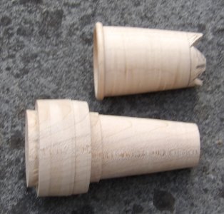
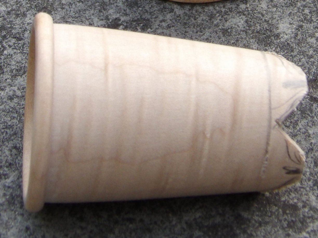
The July Competition was set to produce wood turned item(s) you would find in a Kitchen.
(photos by Rick Patrick & Paul Reeves)
MAY 2023
Bowl from a Plank
with Paul
Reeves.
Thu 18th
May 2023 at MWCC Club Night
There wouldn't be a problem to overcome if the plank was 6" thick!
Obviously we are considering how to achieve a usable bowl with plank thickness less than
the height of the bowl.
Paul had identified 4 possible solutions using thin planks laminated one
above another.
♦ 1 : same sized solid circles in a tower - creates
the most wastage;
♦ 2 : increasingly stepped sized solid circles - still
a lot of wastage;
♦ 3 : stepped sized rings - using solid rings more
efficiently by dividing each into 2 or more rings;
♦ 4 : single solid circle with angled cuts - to create
rings so that the base of the next higher ring sits precisely above the top
surface of the ring below.
Option 4 is clearly the most efficient with the least amount of wastage but
the difficulty is to calculate the correct cutting angle to achieve it.
Consideration must be taken for the width of the tool creating the cuts.
Experience has shown that it is advisable to draw a scaled diagram to determine
the angle.
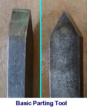
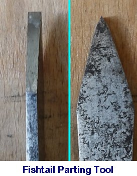
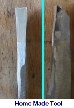
The Fishtail Parting Tool is similar in shape to the Basic but
has a slight thinning shaft behind the tip.
Paul's home-made tool was fashioned like a Bedan Parting Tool (i.e. end
cross-section as shown on the right) together with a more pronounced Fishtail shaped
cutting edge.
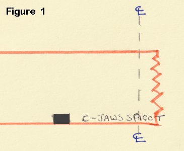 Planning Diagram
As the glued piece will have to be held in a chuck, the first job is to
decide which jaws. Paul had in mind a bowl size that could be held in C-jaws so
worked out where the spigot edge had to be. From that circle, he needed to
cut away a circular groove such that the C-jaws could clear the spigot and go
down to the bottom of the groove to ensure a good grip.
Paul's next decision was to consider a pleasing overall width of
the bowl and its ideal final thickness.
The smaller the angle of the cutting tool, the wider would be the bowl lip; a
large
angle would tend to produce a tall narrow bowl more like a vase.
If one wanted a bowl wall thickness of 12-15 mm, it would give the turner more flexibility
for shaping if the cut thickness was about 10mm wider.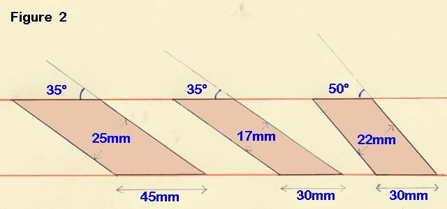
Figure 2 illustrates that the desired bowl wall thickness
is produced by a larger dimension along the surface of the plank.
Additionally, the smaller the angle, the dimension along the plank's surface
needs to be even more.
Paul had drawn an accurately scaled plan of the plank in order to find the correct cutting angle - (xº in figure 3.)
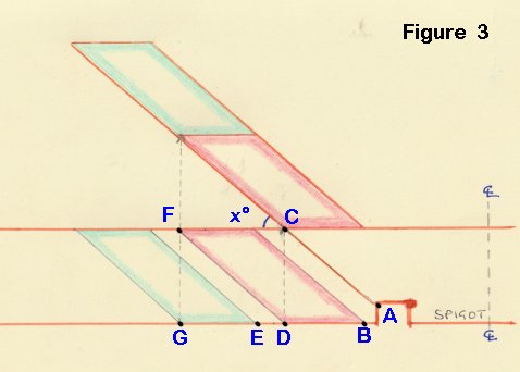
Having found out that his Home-Made Parting Tool would create a
10mm cut, he planned the 10mm cut to run between A and B.
He wanted to go 3 layers high and start with a wall thickness of over 20mm which
would allow him to finish up (after shaping) with a wall thickness of about
10mm.
With these figures in mind, he decided to draw point D exactly 30mm from B.
The whole principle for the second layer to sit precisely on the bottom layer's
outer edge is for point D to end up at point C vertically above it. By
joining A to C, Paul could now measure angle x and found it to be 39º
The same principle occurs with D to E =10mm; E to G = 30mm; Point F can be found
and the angle of the cut is the same 39º
Mounting
Paul used a MDF disk connected to his chuck via a face plate ring. The
MDF provides a sacrificial depth that will help prevent the tool touching the chuck
and causing damage to both.
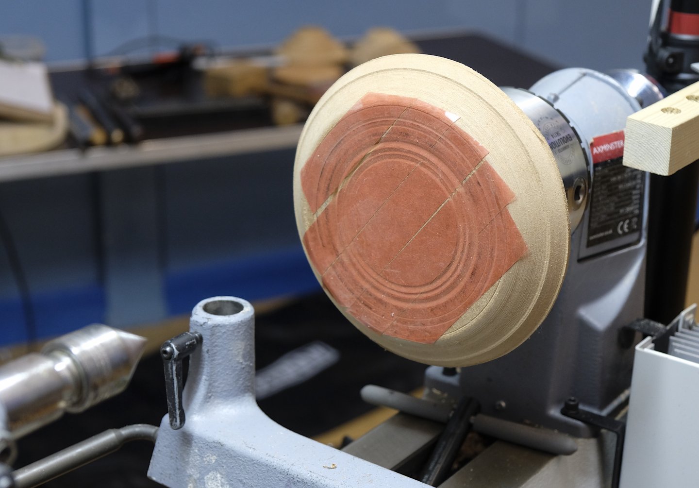
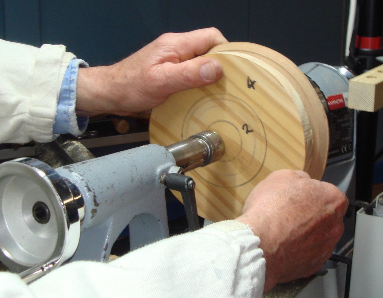
(click any above for close up view)
The piece of plank was secured to the MDF with double sided tape or hot glue.
If you use hot glue, run it out in a 'X' shape across the MDF to ensure all the
rings stay attached when being cut out.
Paul made use of the tail stock to aid getting the plank centred.
The spigot diameter was drawn on the plank and a Parting Tool was used to cut a
groove at right angles into the wood and enlarged to about 10mm wide plus a
small cut-in at the base so the C-jaw would be able to get in to grip the
spigot.
The next 3 cuts were the angled ones all the way through the plank with Paul's
Home-Made Tool. Paul commented that he would start from the outermost cut first
in order to help the inner piece of plank remain firmly stuck in position.
To help keep the tool cutting at the right angle, one could use a slab type tool
rest with the required angle marked on its top face. However, Paul used a
magnetic digital angle tool (from Lidl) which he fixed on the banjo and provided
a straight edge guide he could parallel.
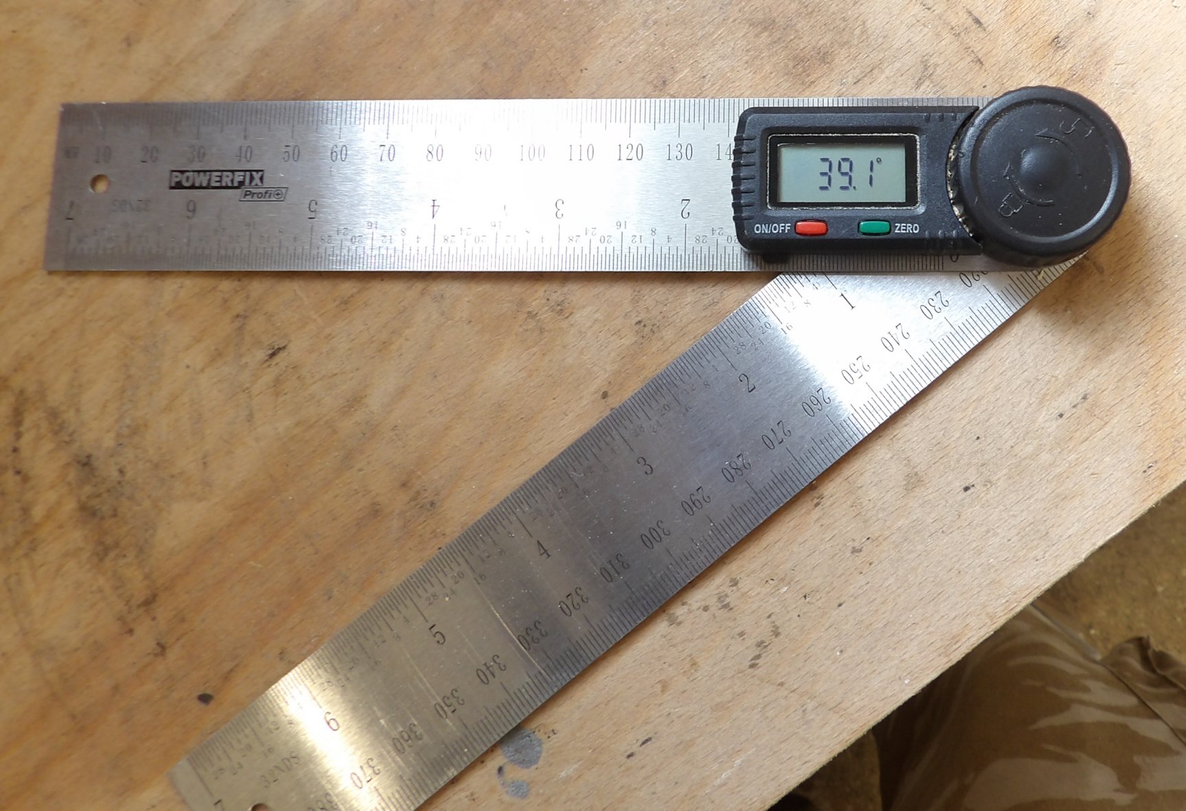
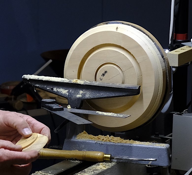
(click any above for close up view)
With the plank cut into 2 rings and a circular base, the pieces were removed
from the MDF faceplate.
Paul had drawn a pencil line prior to turning which would be helpful to get
grain to line up once the 3 layers were turned over and laid on top of one
another before they were glued, making use of the faceplate supporting the top
layer and the tail stock keeping the bottom layer pressed hard against the
others while the glue dried.
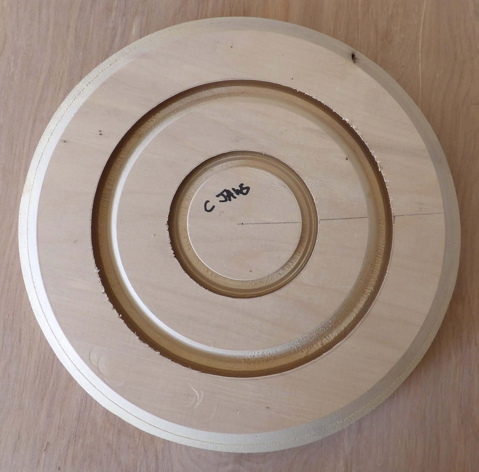
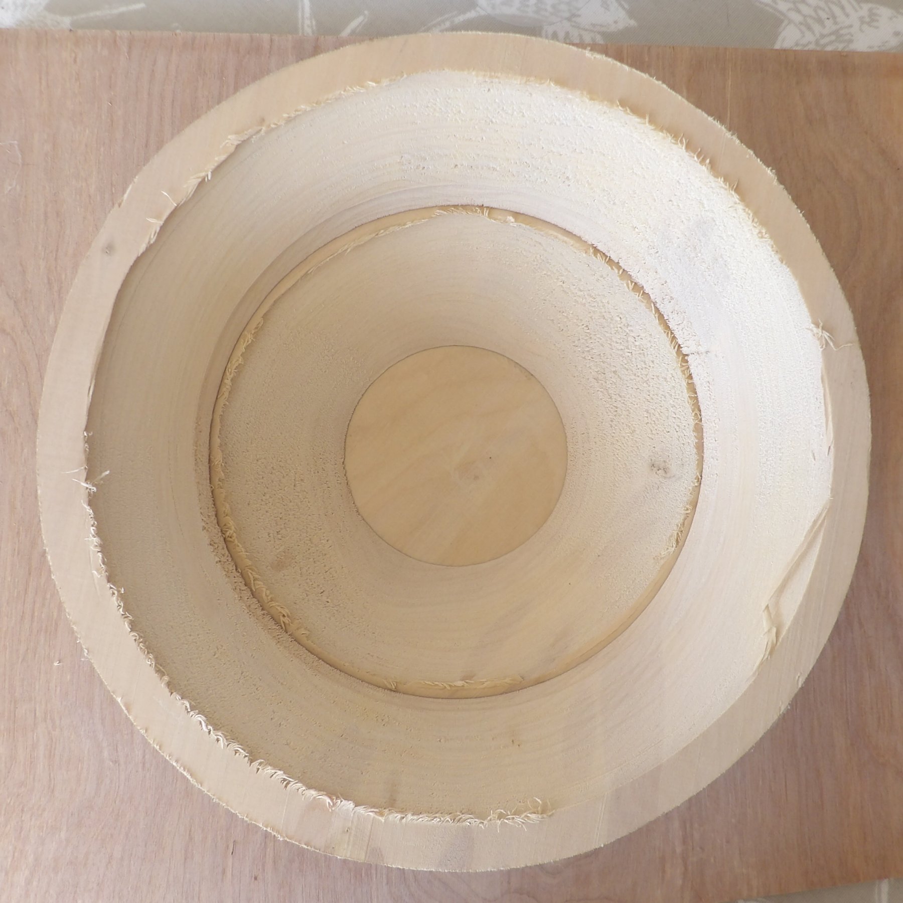
(click any for close up view)
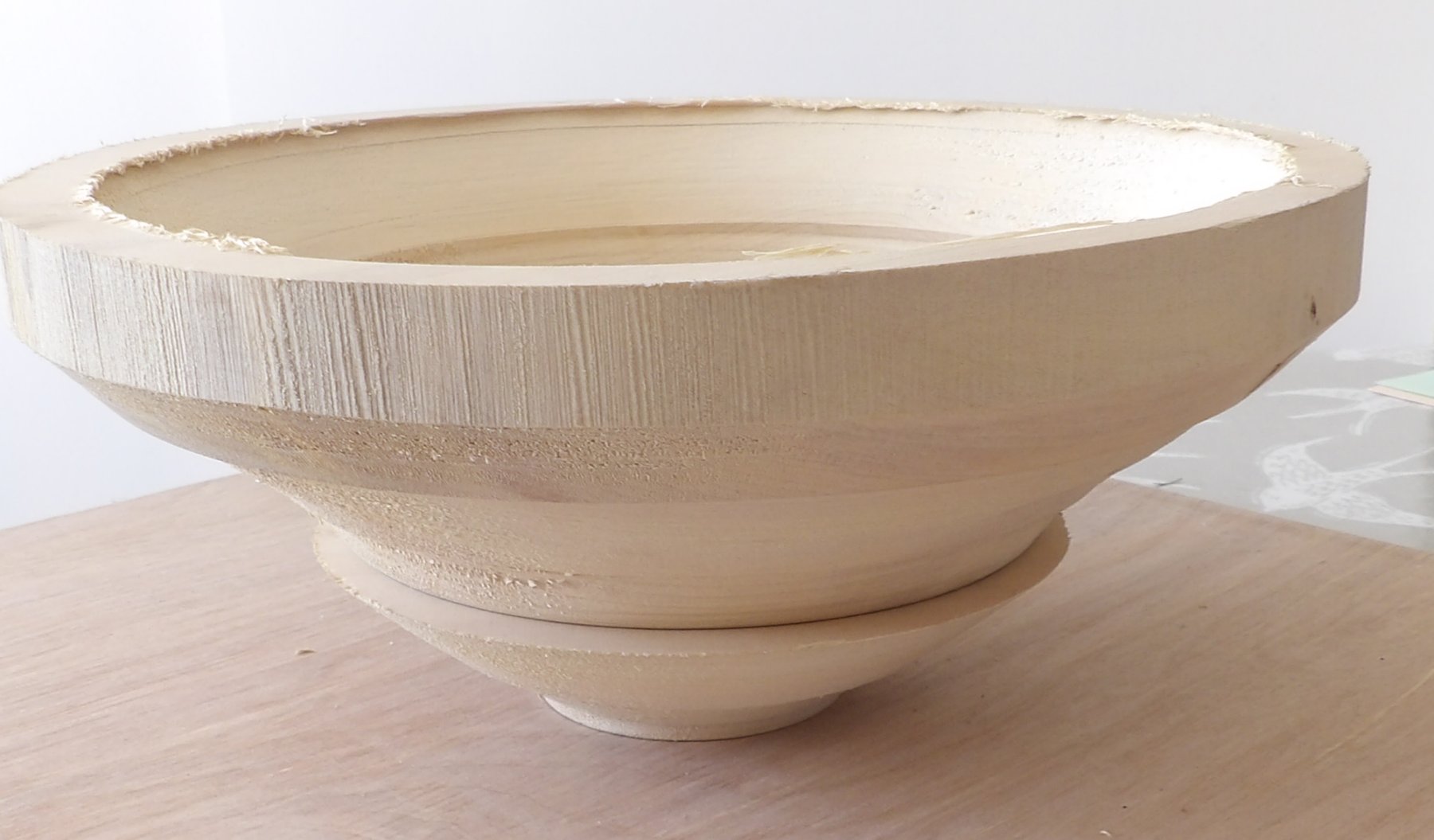
(photos by Andy
Ogilvie, Rick Patrick & Vic Russell)
<to
top>

Andy explained that following a visit to a workshop of fellow Member, David Game, he was fascinated by some twisted polygon shapes known as Streptohedrons (aka Wobble Balls in USA). David had discovered examples on a website by Englishman, David Springett (alas no longer alive).
'Strepto' is Ancient Greek for "twisted" while 'Hedron'
describes a "geometrical solid".
Streptohedrons are created by splitting a piece of wood and re-gluing them
together, turning a shape before splitting and then re-gluing again BUT
only after twisting one of the splits.
After band sawing the wood,
Andy had planed both sides to make sure they made a flat joint. The join is done with
glue (typically PVA) on each joint face sandwiching a piece of newspaper/paper, which will be
strong enough to hold the halves together on the lathe but still be able to
split again despite absorbing glue. Glossy paper should be avoided as it tends
to restrict the absorption of the glue.
Cup centres were used on the lathe in order to reduce the chance of drive and
tail centres prising the piece apart with only their central pins pressing
against the join.
To make a successful Streptohedron, you must plan to have a shape with rotational symmetry (i.e. when a surface can be rotated and it exactly matches its starting surface) so that when the halves are twisted to the desired symmetrical position, the joint faces will still fit following shaping with your turning tools although some sanding will probably be required.
StreptoHex
Andy had selected a 3" cube of Yellow Ash, which
he had prepared at home by band sawing it in half, gluing as above, mounting between centres (with the
joint running from head to tail stock) to turn a spigot for his chuck (which
helped to secure the glued halves together) and finally turned
to a cylinder so that the length exceeded the diameter sufficiently to allow
space for working tools at the drive centre end of the piece.
This was mounted on the Club's lathe. The cylinder was trued up; the end was squared off and the final diameter measured. His plan now was to turn the whole piece so that the join surface changed from its rectangular shape into a 'regular' hexagon, which required either a bit of technical drawing or some mathematics to work out the correct dimensions.
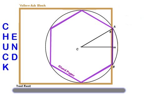
From the diagram above, he needed to work
out the lengths of AB and Cm.
Since Andy had just measured the diameter, he could calculate the radius (AC) and drew a
circle with compasses (either at true measurement or scaled) on a piece of
paper. Choosing a convenient point on the circle, he marked 6 arcs along the
circumference using the same compass with the circle's radius to map out the 6 corners
of the required purple hexagon above and measured the two required lengths.
Alternatively using formula & trigonometry, the
internal angle in degrees of a regular polygon with 'n' sides is 180(n-2)/n. A Hexagon's angle
is therefore 120°, which means angle 'a' = 60° and the triangle CAB must be
equilateral, so AB is the same as the radius AC. From trigonometry
Cm = AC x sin60°(which
is 0.866)
Andy's demonstration piece had a
diameter of 60mm,
which meant AB was 30mm and Cm was 26
The cylinder was marked up with a centreline 26
mm from the newly squared off end and another mark 26mm closer to the head stock, which would define the other end. Finally, a 30mm circle was marked on the cylinder's end.
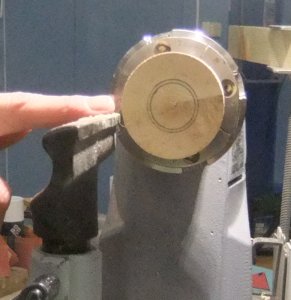
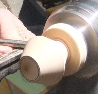
Starting out with a Spindle Gouge and finishing with a Skew, Andy turned away the Ash piece to leave a smooth cone shape between the centreline and end surface circle marks. Using his parting tool, he started to part the piece at the head stock end to the same depth as the end face. For our demonstration piece, that depth was to leave a 30
mm circumference which he had set on his callipers. Andy then gouged out between this last cut and towards the head stock to give himself room to turn away a matching smooth cone shape towards the head stock.
(some photos in this
demo can be clicked for close up views)
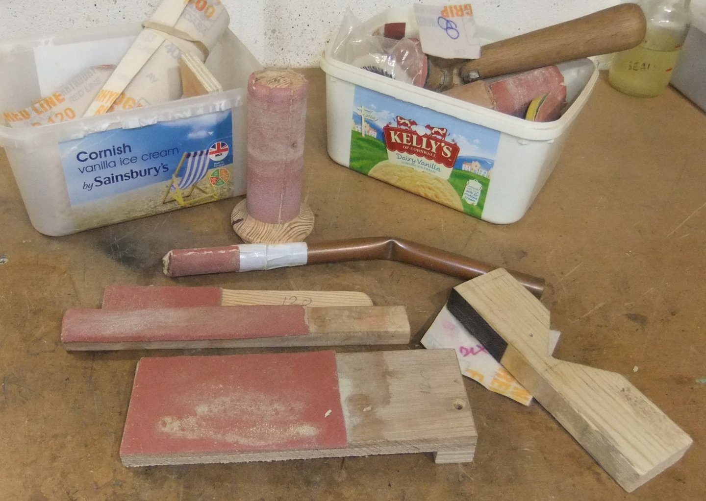
Andy had a selection box of different shaped sanding blocks so he could sand all flat surfaces carefully without damaging any sharp edges/corners. He then sealed all surfaces with Sander Sealer before applying some Yorkshire/Hampshire Grit to smooth and polish using his applicator of choice - his old socks!
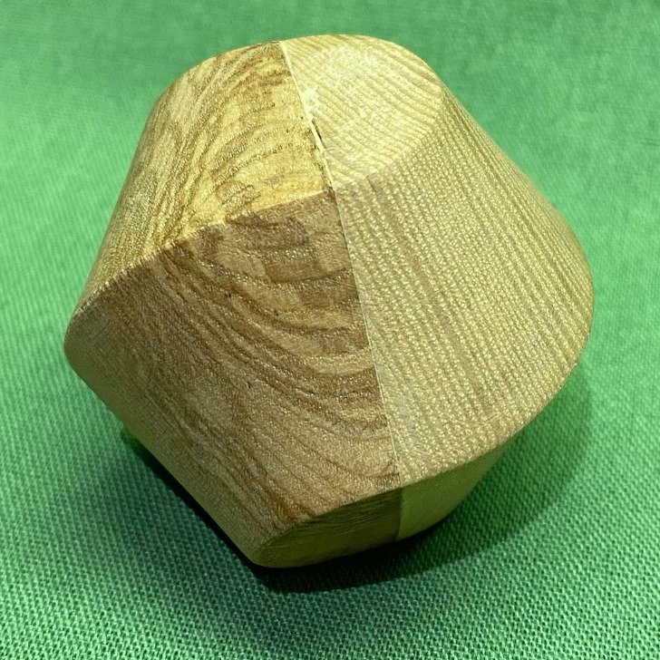
Femisphere
As with the previous demonstration, a blank block (this time of Mulberry) had
been prepared by being band sawed in half, re-glued, spigot turned with the
split running from head to tail stocks.
The prepared blank was now mounted on the Club's lathe & chuck where the
cylinder was trued up, the end squared off and the final diameter measured.
Instead of a hexagon, the Rotational Symmetry face this time would be a
distorted plus sign.
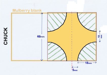
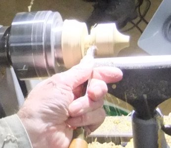
From the diagram above, you
can see that the blank was turned to a cylinder that ended up as 46mm
in diameter.
The plan was to turn away identical quadrants to leave 10mm
edges at each cardinal point. This meant that each quadrant would have an 18mm
radius. The cylinder was marked at 18mm, 28mm
and 46mm from the tailstock end plus a 10mm
circle drawn on the end face.
Andy admitted that he had deliberately arranged for the cylinder to be reduced
to 46mm because he already had a 36mm
button in stock, which would act as a perfect template in keeping the curves
identical on each end of the piece.
Working on the tailstock end first with a Spindle Gouge to get a curve close to
the first mark and the 10mm circle, he finessed the work
using a Round Nose Scraper with regular checks against his template button.
Before starting the headstock end, Andy parted down towards a 10mm stub at the
46mm mark and turned away waste to make space when using
his gouge/scraper. This needed gentle passes of the cutting tools because of the
weakened support from the reducing stub size as he progressively parted away. (There
are some Conical Tip accessories for live revolving centres which would improve
support.)
He subsequently needed to create more space in front of the stub to accommodate
checking with his rigid template.
Once the inner quadrant shape was finished, he parted off purposely leaving a
small nib and proceeded as in the previous demonstration with effect from the
TOP TIP : above and ended with the rather tactile shape shown below.
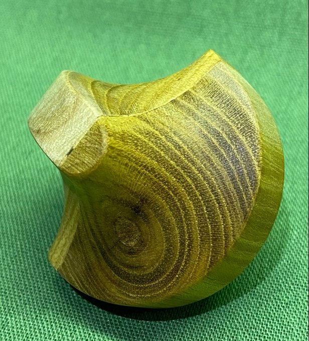
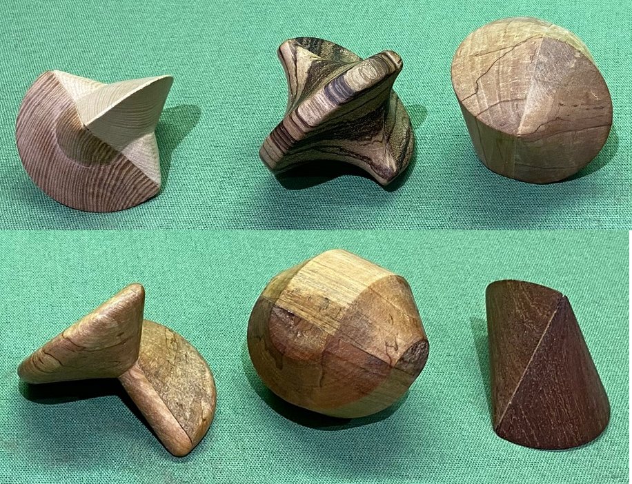
Bibliography:
David Springett : 'Woodturning Wizardry' & 'Adventures in Woodturning'
The
Bridges Archive - < link >
(photos by Andy
Ogilvie, Rick Patrick & Vic Russell)
<to
top>
January 2023 -
DEMO 5
Buttons
with
Paul Reeves
Thu 19th Jan at MWCC Club Night
Why would anyone want to turn buttons?
They are readily available very cheaply from shops/internet although they
generally tend to be of poor quality. If you have turned them yourself,
one commonly thinks of them as something special.
For example, the Wife of one of our Members makes bespoke handbags/clutch bags,
which are elegantly finished with a stained or natural wooden button to
complement the design and avoids that 'mass-produced' look.
Coat Toggle
One of the simpler fasteners is a 'toggle' commonly used on Duffle coats.
Paul had a piece of composite ply made from compressed colourful Maple prepared
between centres, which he turned to a cylinder. He then marked out the two
ends and the centre appropriate for the intended button hole/loop. Over the
years, Paul had fabricated his own scraper-type tools from old chisels and even
from a 1" wide commercial hacksaw blade, although that had to be heated several times to reduce its brittleness.
Having selected one of his homemade scrapers, Paul skewed from centre towards
each end to shape before finishing out a cove around the centre to accommodate
the fixing twine using a gouge.
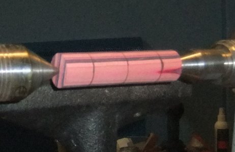
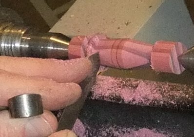
Drill Jig
It is difficult to drill sewing hole(s) accurately and get each button looking
identical. Any misplacement will appear obviously out of square. Even with
a single toggle hole, the starting hole is easy but difficult to get it to
emerge within the cove on the opposite side. It is well worth preparing a Drill
Jig to fit in your tool rest banjo and thick enough to provide a pilot hole
which will hold a drill bit to turn steadily without any wobble.
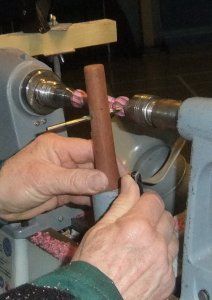
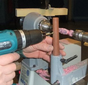
Paul took advantage of the lathe's ability to lock the chuck into a
fixed position and used a 5mm drill for this size of toggle.
With the shape & hole completed, abrasives were used through the grits, (finishing off
by being applied along the grain). Some wax / friction polish / lacquer
could be applied before parting off. In order to get a clean cut to the
toggle ends, Paul used a Skew Chisel with its point downwards.
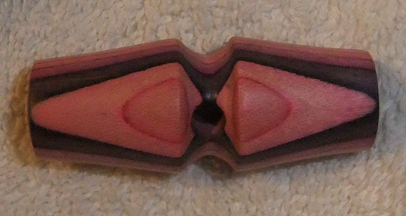
(click this
photo for close up view)
Small Buttons
To make a production line of identical small buttons, it is best to turn a
cylinder of wood to the diameter required for the button hole and mount in
o'Donnell jaws. Paul had chosen to start the demonstration with end grained wood
which needed to be a hard wood like Box (as lesser
close grain woods will probably be too brittle). As small thin buttons
have little wood to waste, the turner needs to reduce the number of abrasive
passes, so keeping tools sharp and regularly diamond-filed will help.
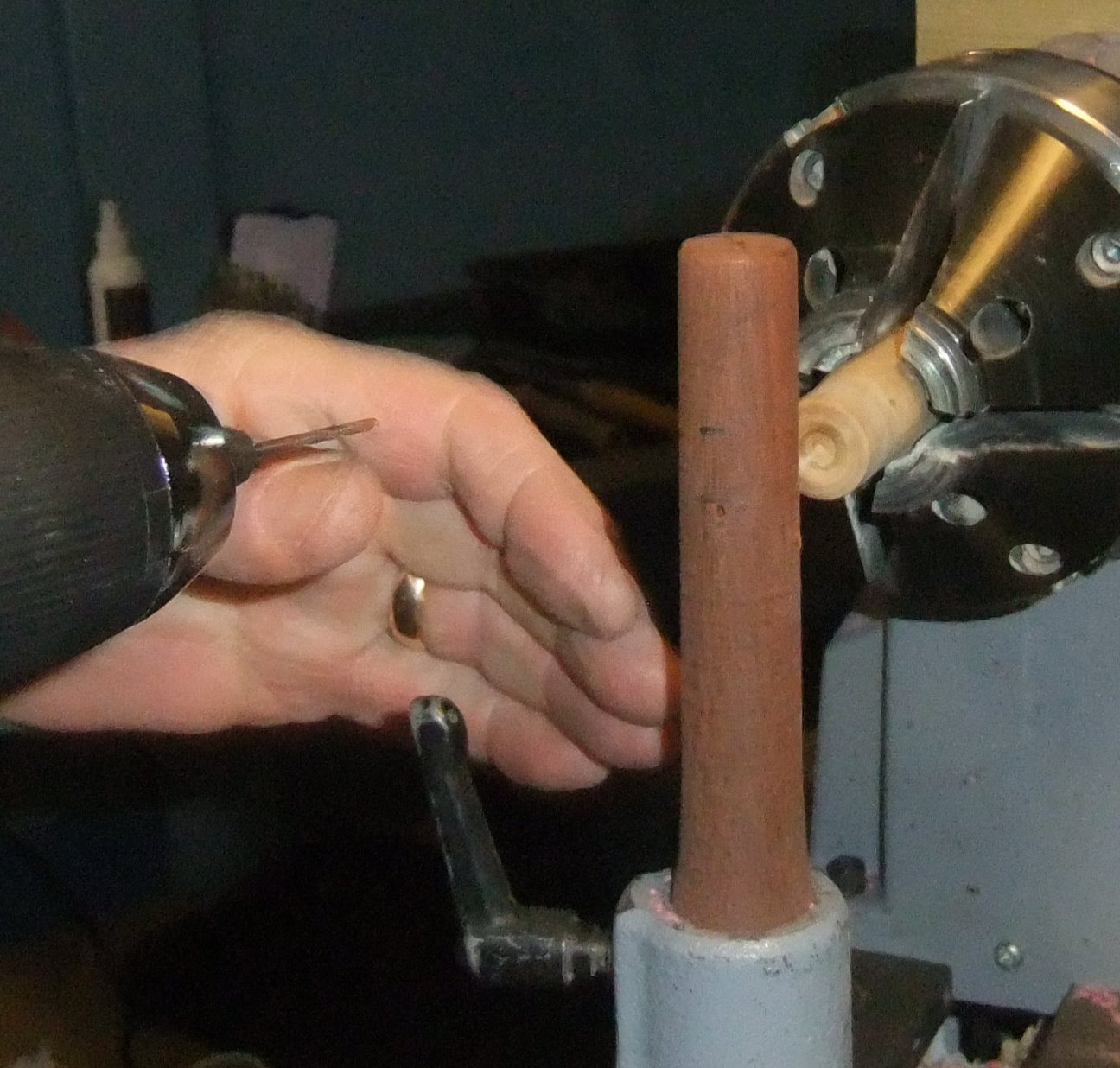
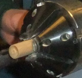
Having squared off the exposed face, Paul turned a shallow dent
in the centre of it to allow room for stitching to be wound through the sewing
holes without adding thickness to the button. He then rounded all corners to
help the button pass through its button hole.
The sewing holes for this size button needed a 2mm hole in the Drill Jig. The
pilot hole was adjusted so that the drill
was lined up parallel to the lathe rails and at a height that
would start just inside the shallow dent. As there were 4 holes to drill,
Paul hand turned the chuck until the gap between adjacent jaws was vertical
before locking the chuck position. When ready to drill the next hole, turning
the chuck to get the next gap upright meant it had turned 90º
and so on. Paul advised not to be tempted to drill deeper than needed for
a single button because the further the drill bit is away from the pilot hole,
the more likely it will wander from the required position for the following
buttons.
Paul parted off with a narrow parting tool but said he was ready to support the
button face with a finger in order
to avoid 'chatter' marks. He also warned to go steady when parting through
the sewing holes to avoid 'pull out'. It would also help preserve the
stitching by chamfering the edges of the holes with a slightly larger drill bit.
Larger Buttons
Any button over about 2cm diameter lends itself to added interest, whether that
be from using interesting pattern/coloured cross grain wood; or using decorative
tools (eg Chatter Tool, Decorative Elf etc) to create patterns; or using
colours/waxes (eg ebonizing, Liming) to fill in or frame the buttons.
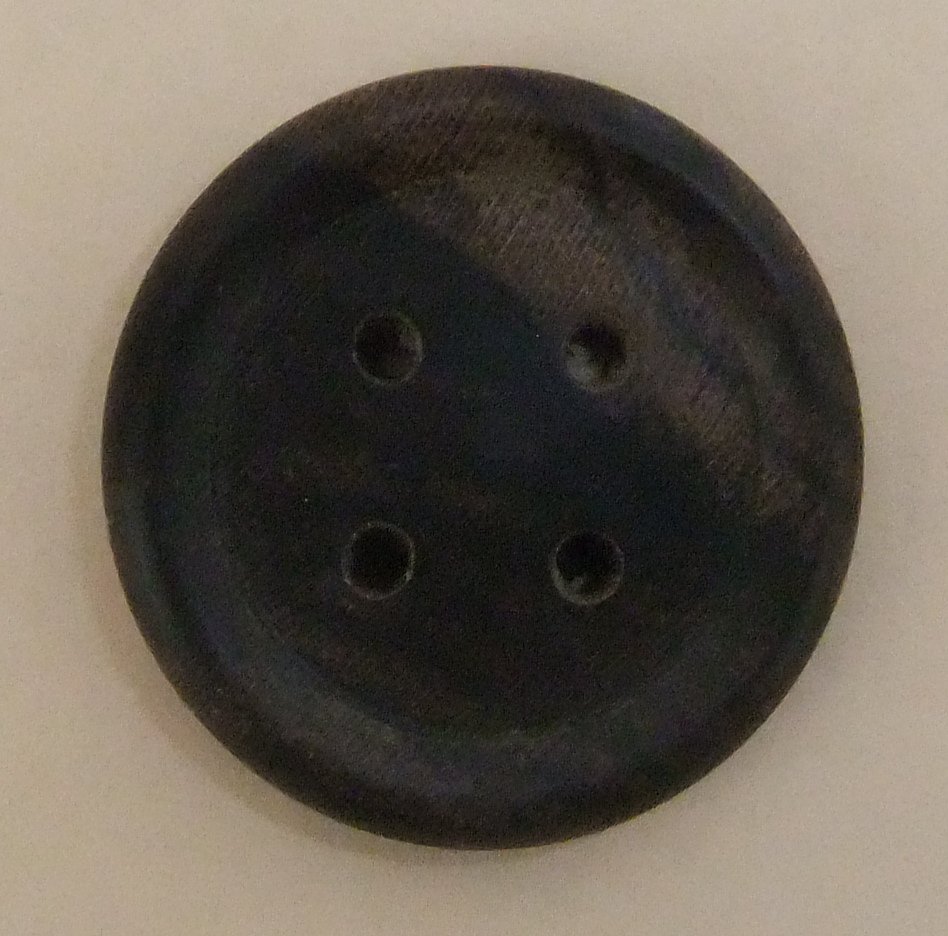
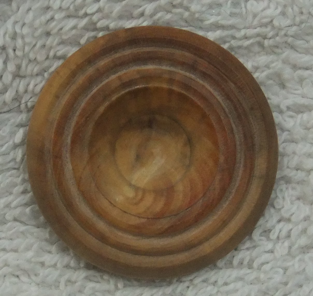
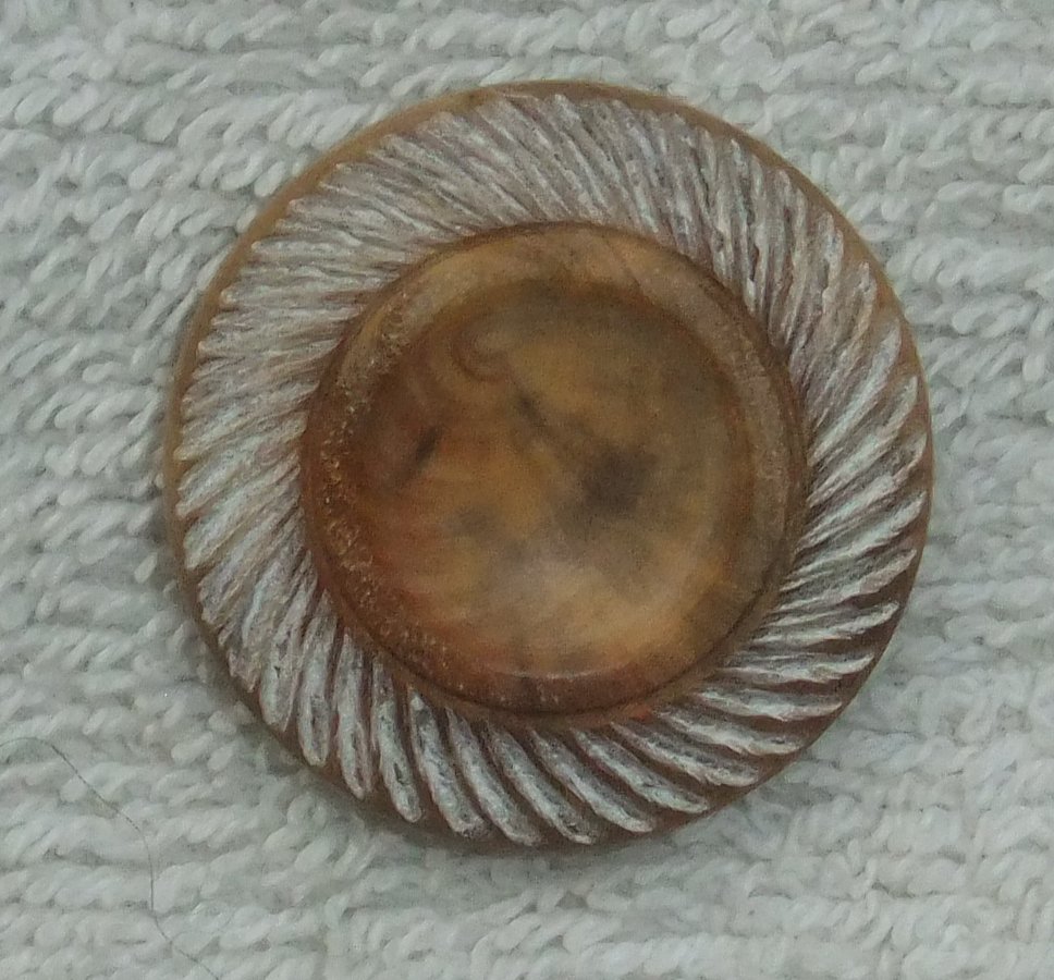
(click any above for close up view)
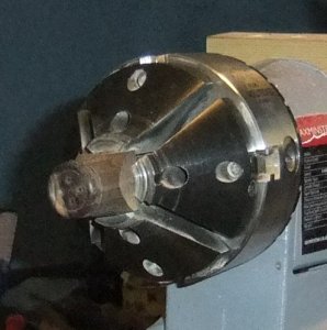
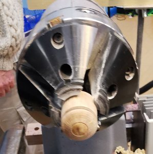
With slightly larger blanks,
sometimes you are able to mount them in the gaps between the o'Donell jaws while
still square.
As with the Small Button procedure above :- turn a cylinder; trim end up square;
dent with slope down towards button edge; pencil mark circle for where holes
will be drilled. Any texturing should first have its preliminary surface
taken to its final finished standard.
Next, apply your decoration, colour or wax before drilling holes and parting
off.
Top Tip
:
In order to avoid damaging the
detail created, take care when using abrasives / cutting paste/ buffing.
In the case of waxes, apply Acrylic Sealer before any other finishes.
Shank Buttons
These buttons have a fixing hole within a post on the back of
the button rather than on their faces.
The technique when using a Chatter Tool is to have a slower speed & move
the tool rest further away than for a gouge.
The shank was formed with a Parting Tool once the face was finished. Paul
created a 5mm shank to accommodate a 2mm fixing hole.
He used a Skew (with point down) to part off.
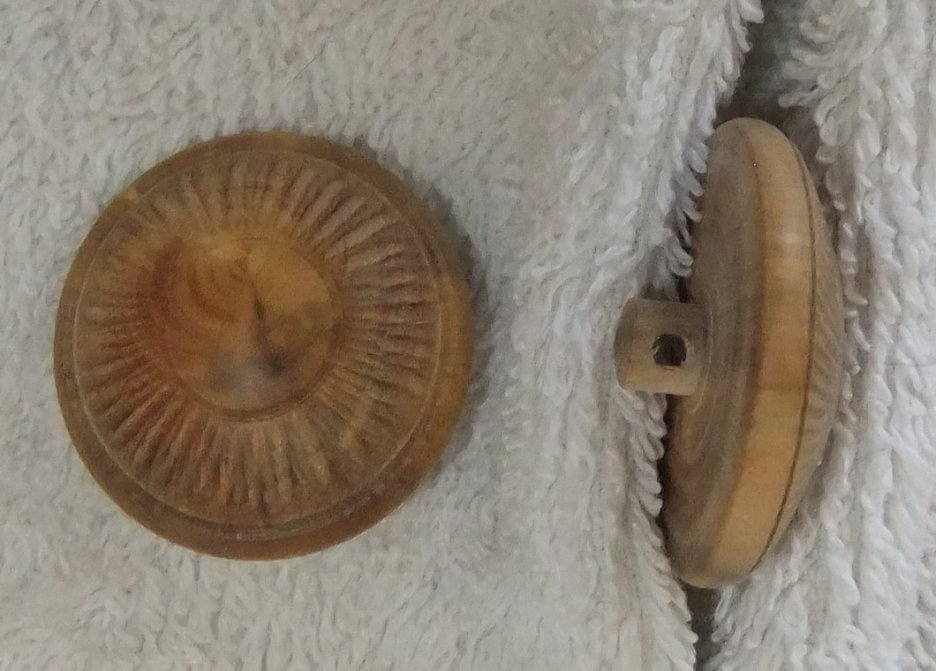
The January Competition was set to produce at least 2 examples of
buttons/fasteners turned out of any appropriate material.
(photos by Andy Ogilvie, Rick Patrick & Paul Reeves)