DECEMBER 2022
Wood Thread
Cutting with a
Screw Box
and
Tap
with Paul
Reeves.
Thu 15th
Dec 2022 at MWCC Club Night
(click any photos in this
demo for close up views)
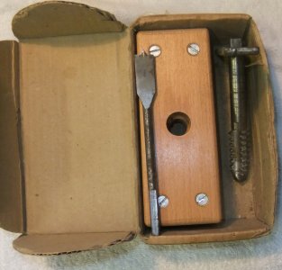
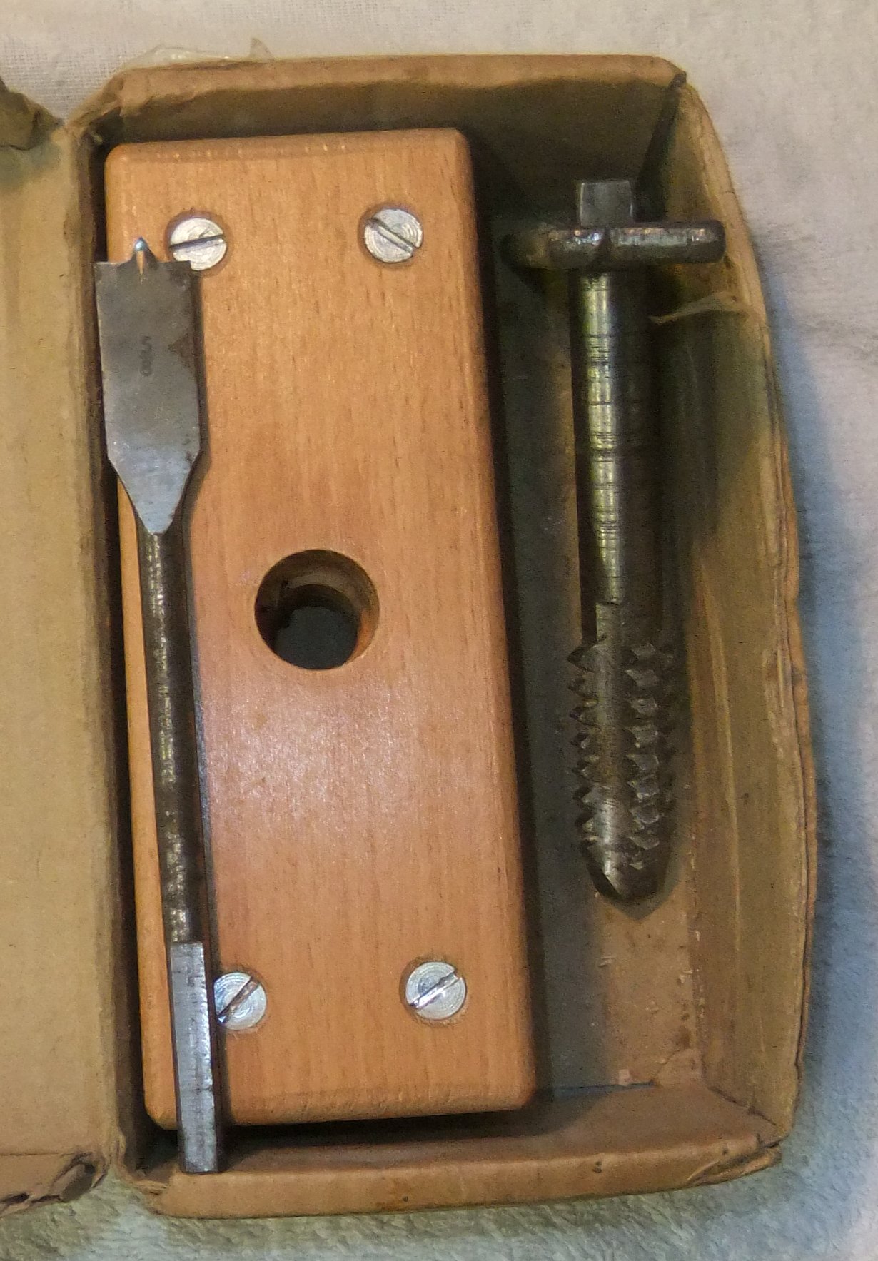
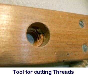
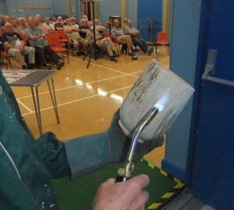
You will need a matching set of Screw Box and Tap.
A size suitable for cracking nuts would be about ¾" diameter.
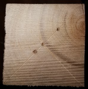
A close grain wood would seem a better choice but Paul has had mixed results
when tapping into hard wood end-grains as the resulting threads would often
crumble away.
He found that threads were more sturdy when cutting across grain for hard woods.
TOP TIP
: If using soft wood, tap
into the end grain after allowing some thin supaglue to soak into it. This will
stabilize the resulting action of the cutter as it produces a thread.
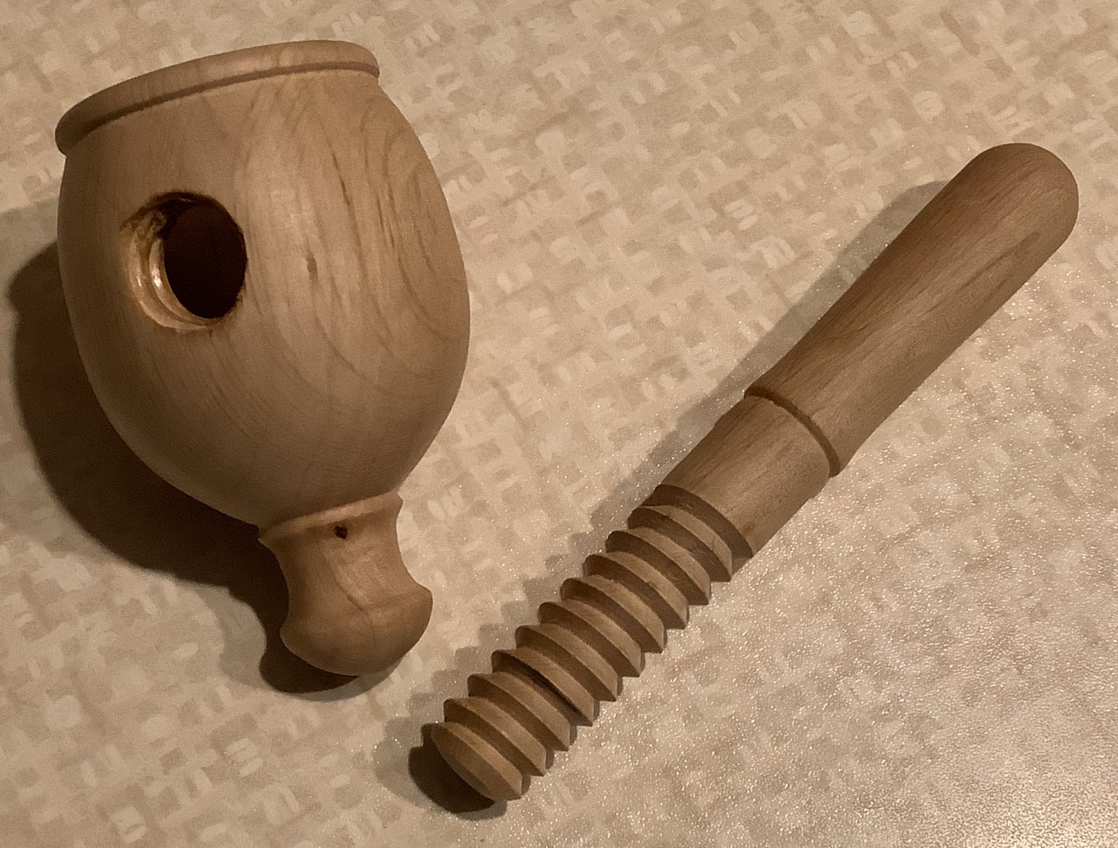
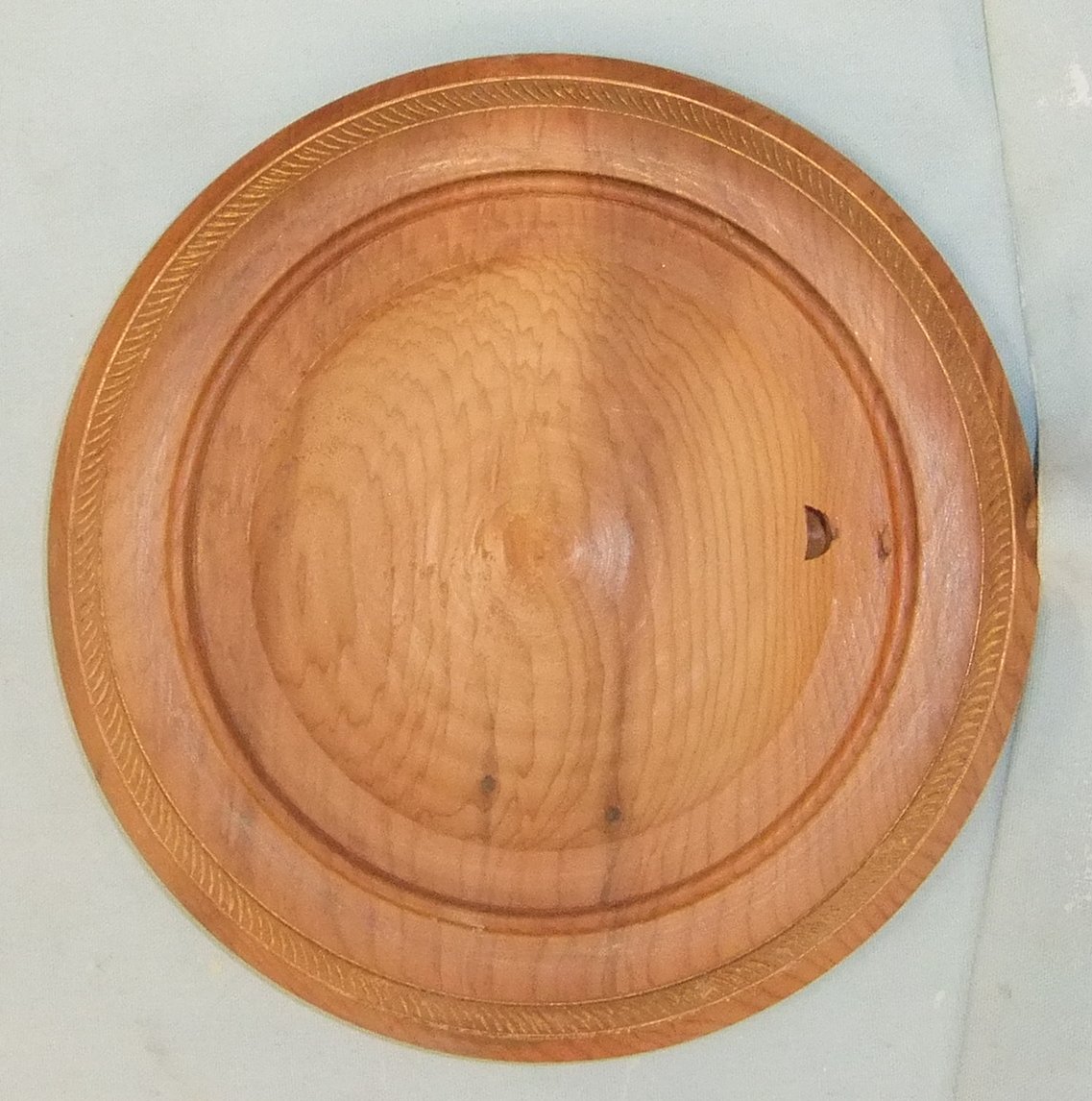
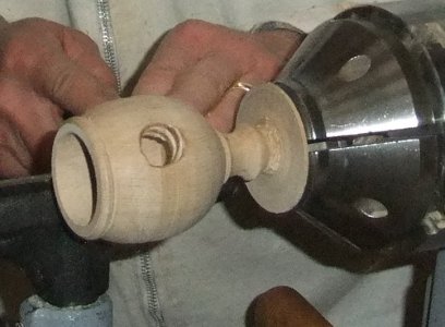
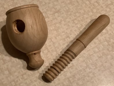
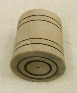
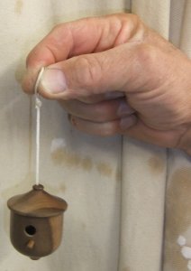
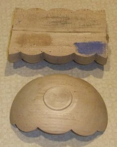
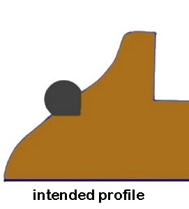
Making a Nutcracker
The Body
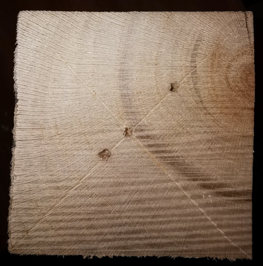
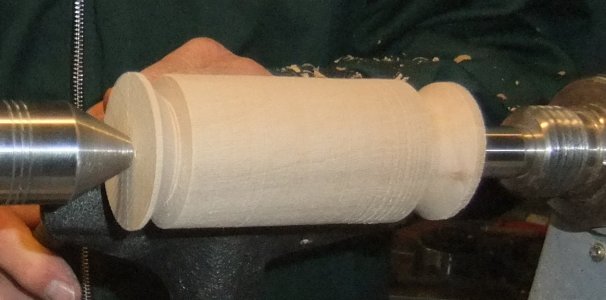
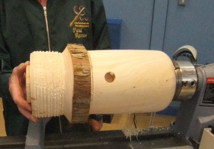
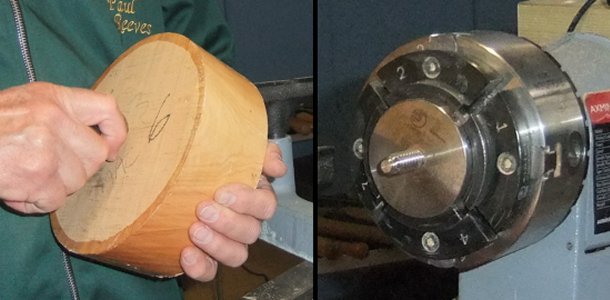
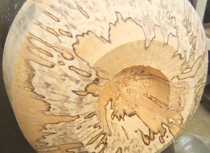
For the demonstration Paul had prepared
a 3" square by some 6 to 7" length of Hornbeam to mount into a chuck.
The width of the holding bowl will depend upon which nuts you are intending to
use : small nuts like almonds/hazel nuts would need about 1" diameter whereas
larger nuts like walnuts would need more room. (Probably best not build one for
a Coconut!)
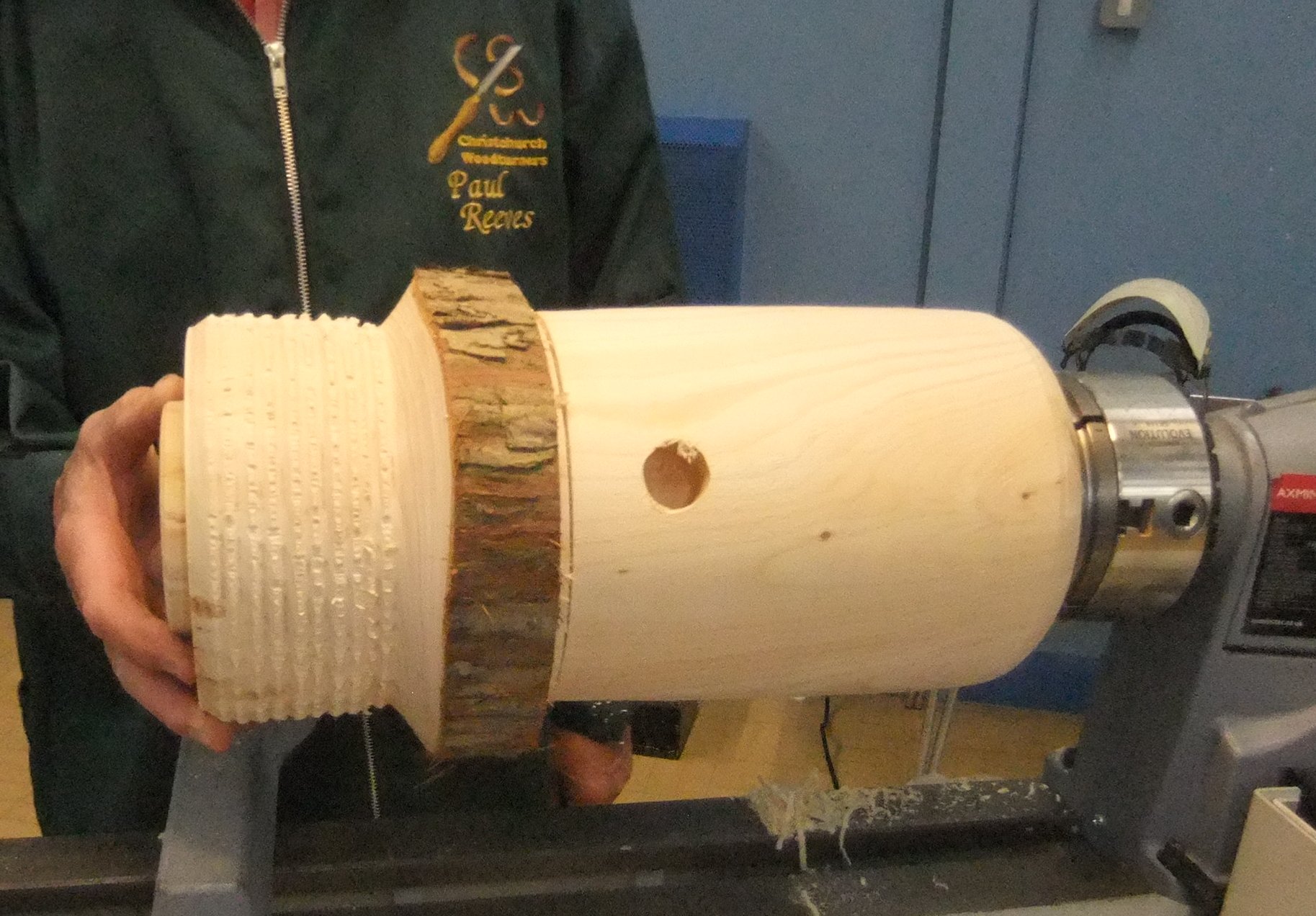
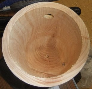
In order to accommodate walnuts, Paul fixed an 1¼" diameter Forstner bit into a
Jacobs Chuck held in the tailstock marked for a depth of about 2" - this would
allow the walnut to be inside enough to be held steady rather than catapulting
out the opening when applying pressure with the screw crusher.
With the bowl hollowed, the Forstner was removed.
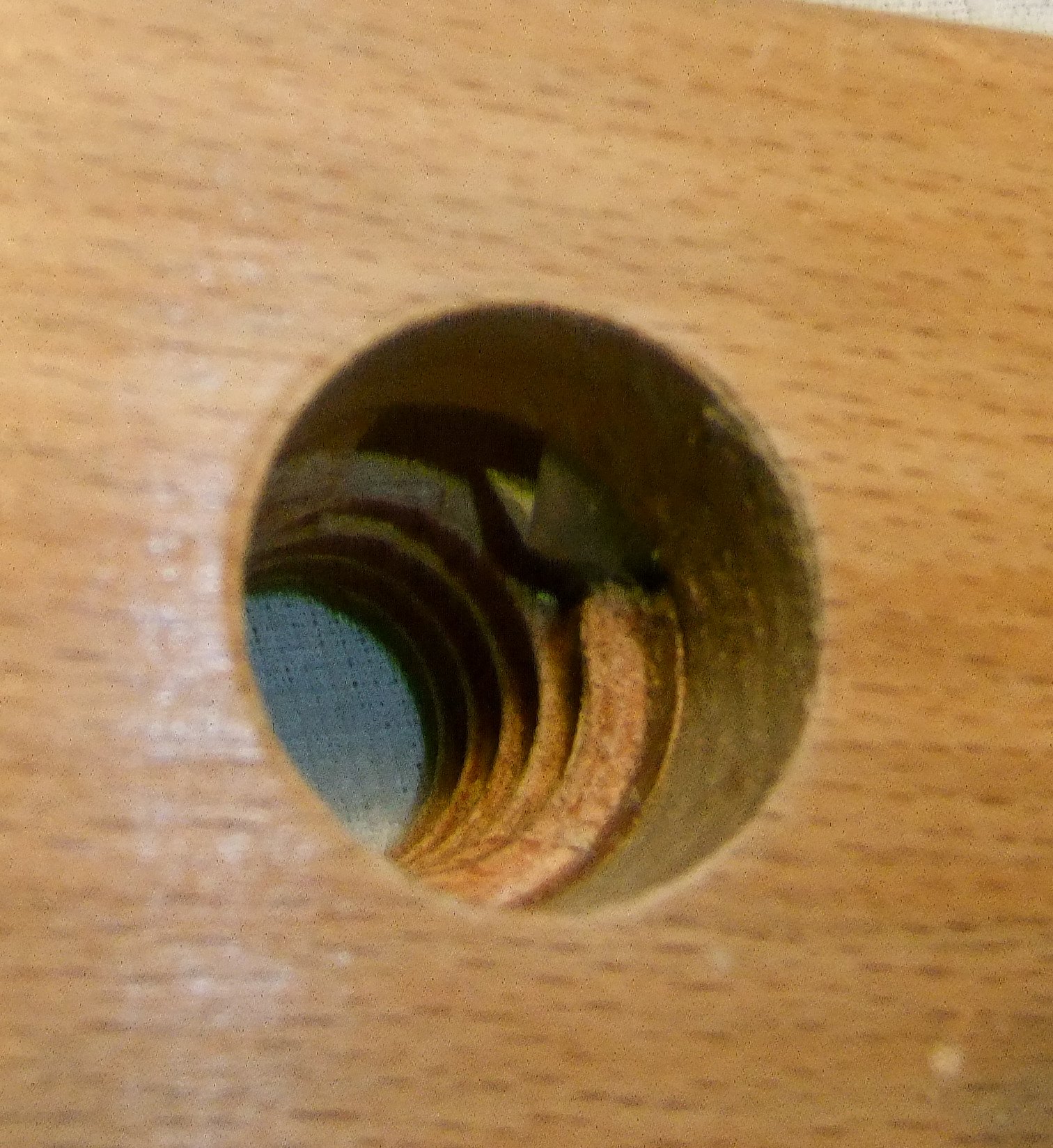
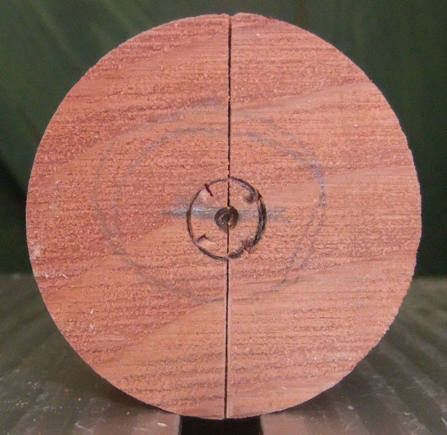
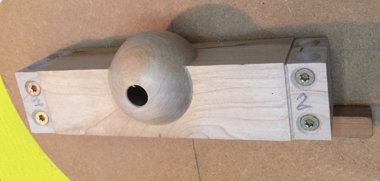
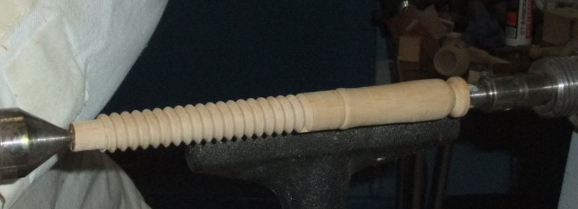
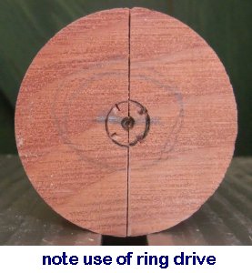
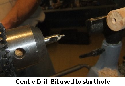
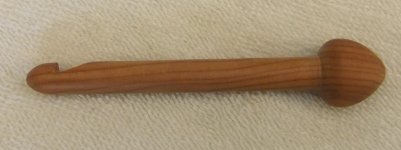
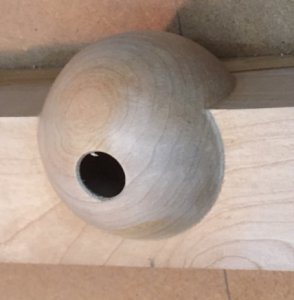
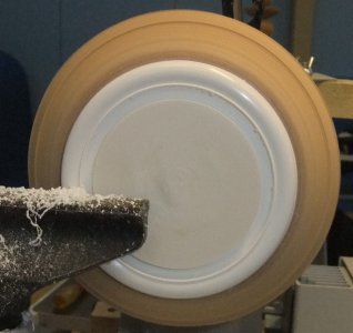
A hole in the side was drilled with a size slightly less than the Tap's
diameter. (If you study the photo above for the ¾" Screw Box, you will
notice Paul's Father had placed a ⅝" flat
hole cutting tool as a starting point but Paul chooses to use a slightly larger
Forstner)
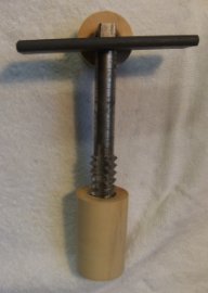
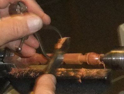
The Tap is going to form the female thread. Once the Tap has started a thread,
it will need to be reversed a quarter of a turn after about every half turn in
order to clear the cutting debris.
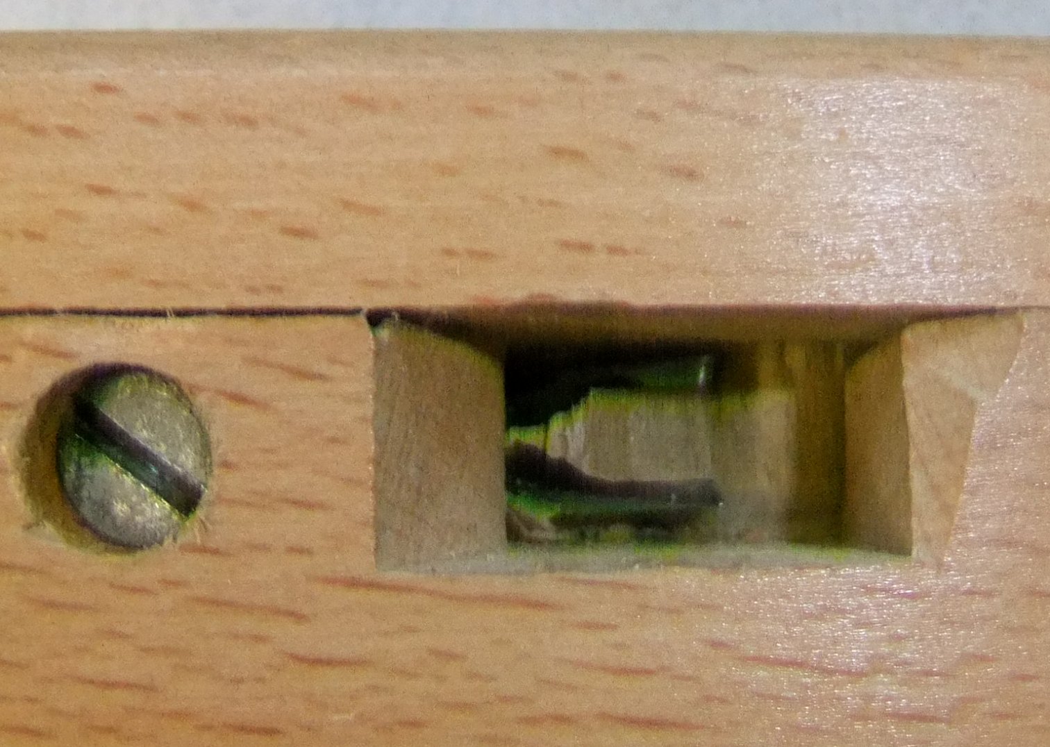
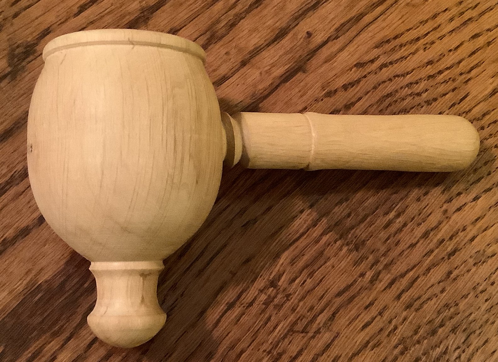
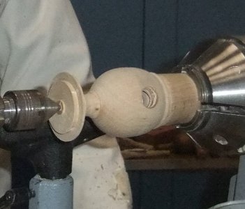
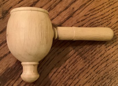
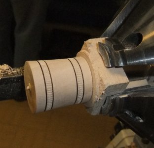
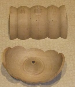
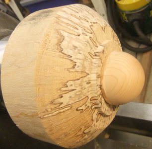
With the thread completed, the outside was turned and shaped into a barrel with
the thread hole at the fattest dimension.
TOP TIP :
When your gouge passes over the thread hole, you will
need to avoid any excess weight into the wood or else you will end up with a
dent/cove in line with the hole.
Keep a check where the bottom of the hollowed bowl is relative to the outside in
order to avoid shaping the handle too close and weakening the piece.
Abrasives were used through the grits but again, being careful of around the
thread hole or else it would end up elongated. The first grit has to rid the
scratches left by the gouge, while the finer grits get rid of the previous
abrasive marks.
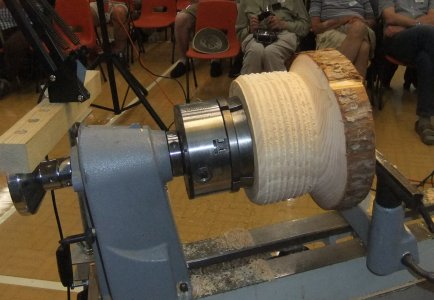
The piece was turned around and a Jam Chuck was used to drive via the Forstner
hole.
The original spigot was turned away to a thin support, but strong enough to
maintain the piece against the Jam Chuck. The thin support was sawn off and
abrasives applied to finish.
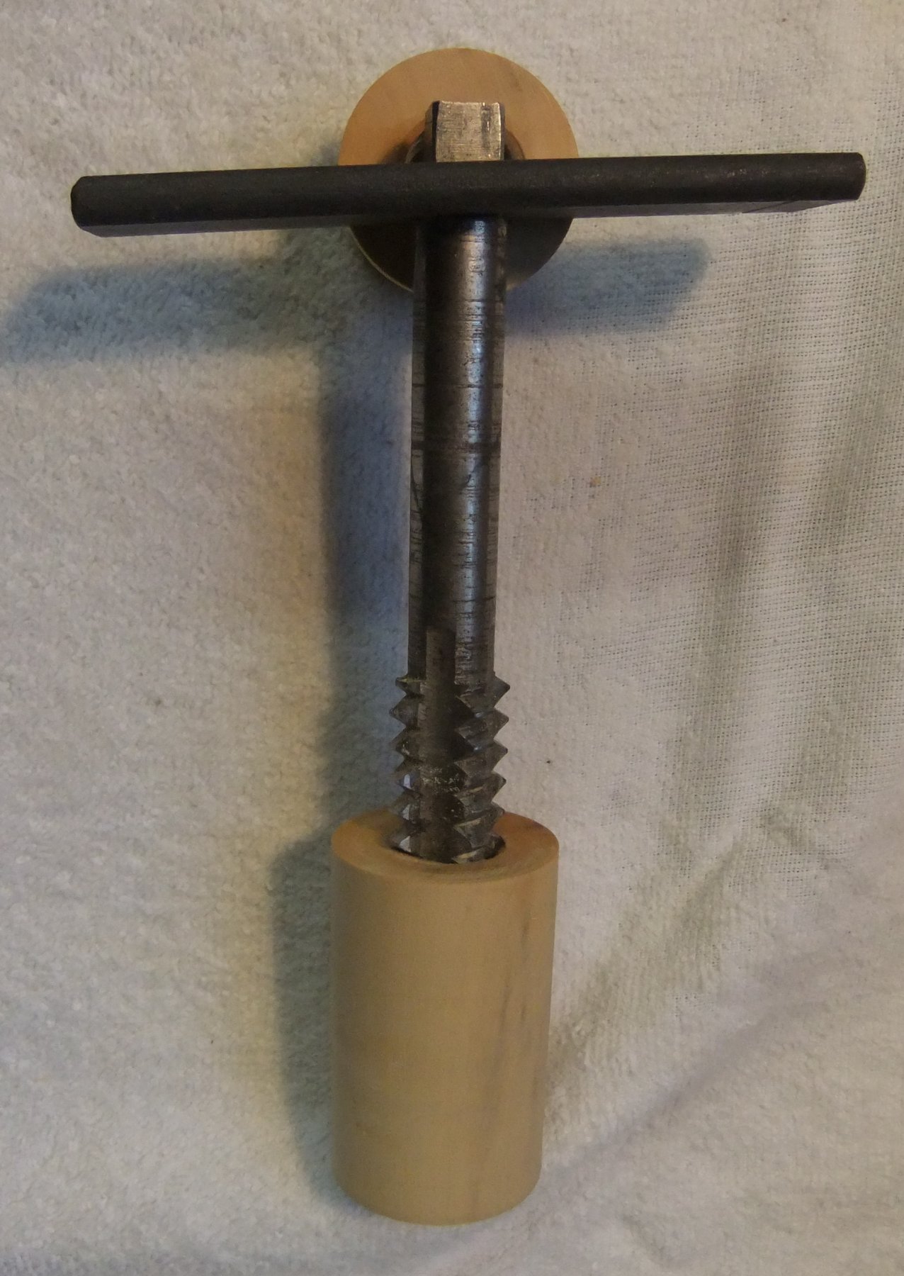
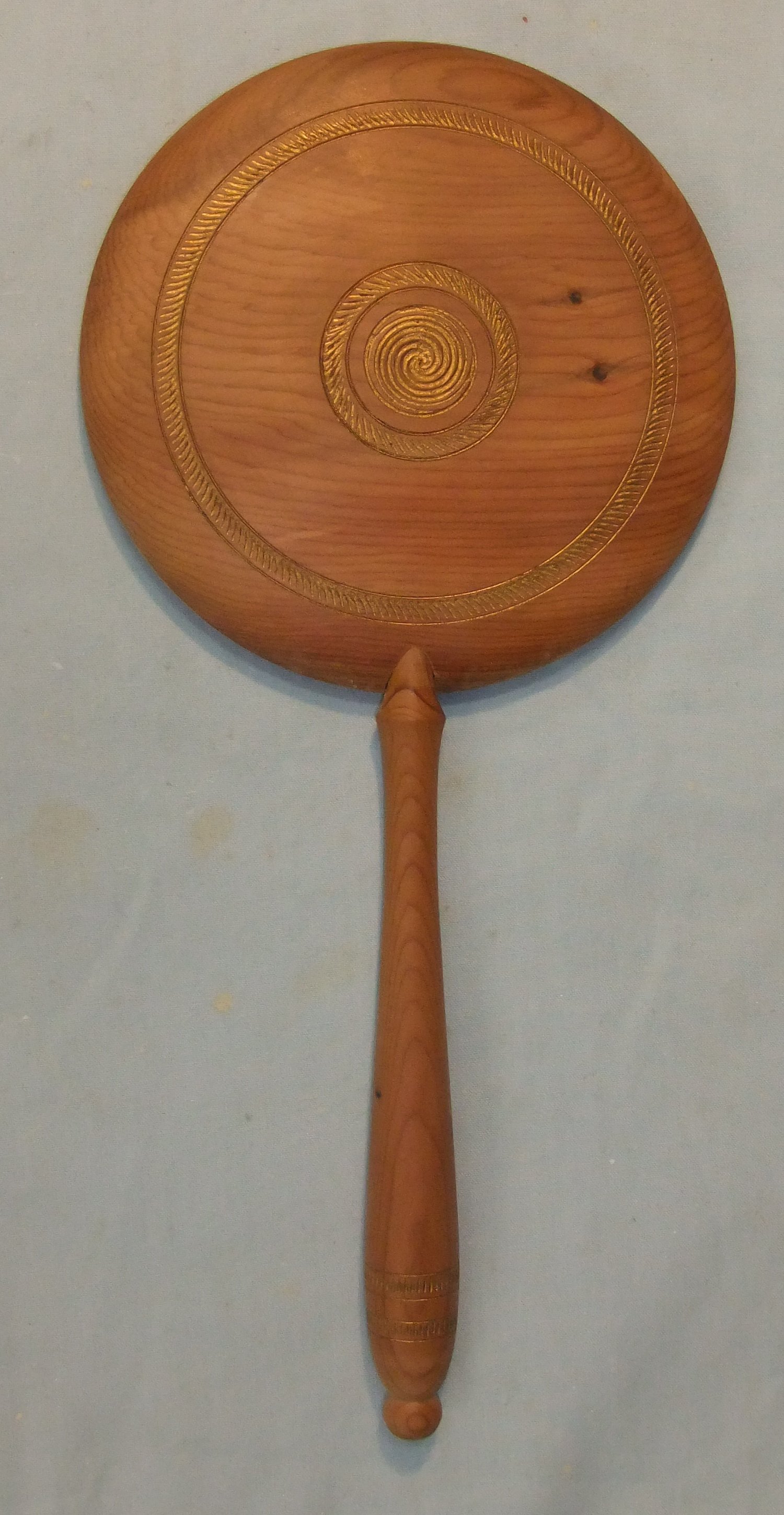
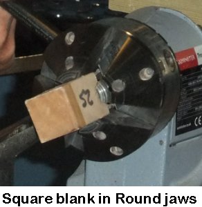
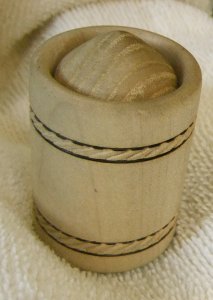
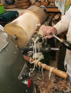
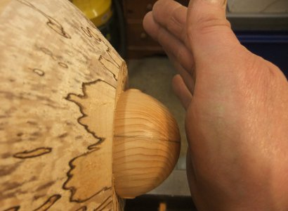
The Crusher
A square blank of Hornbeam about 8" long was mounted between centres and turned
to a cylinder at the required diameter for the chosen Screw Box size.
The length of thread required on the dowel was measured from the outer edge of
the bowl though the thread hole to the opposite inside edge. A further 1" was
added to compensate for the distance the dowel has to go into the Screw Box to
reach the thread cutter, which creates the male thread, and for the space of a
chamfer to be turned at the end point of the thread (to help avoid damaging the
thread as it contacts the nut or else the curved inner surface of the bowl).
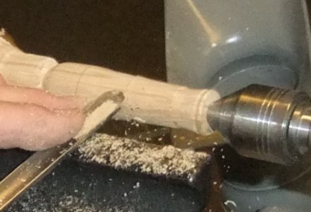
This is best achieved accurately by use of a Skew Chisel held with the long
point down.
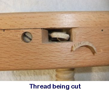
Unlike the Tap procedure, the Screw Box
technique requires turning the dowel in the same direction (without any quarter
turns in reverse) so that the off cut exits the box without breaking off and
jamming inside.
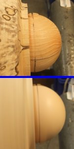
A handle was then turned and sanded before being sawn off at the chamfered
bottom of the thread and at the top of the handle.
TOP TIP :
If using softer woods, a hard tip could be added to the
bottom of the thread with a hob nail or gluing a button of hard wood, eg Box,
Rosewood etc.
(photos by Rick
Patrick & Paul Reeves)
<to
index>
October 2022 -
DEMO
4
Animals
with
Paul Reeves
Thu 20th Oct at MWCC Club Night
The Internet can show a confusing scrapbook of
examples but googling, for example, "animals for wood turners" should be able to
give you more focused ideas.
The challenge to produce something unique is to see a picture of a finished item
and then use your experience and wits to work out how to achieve it rather than
just following instructions from start to finish.
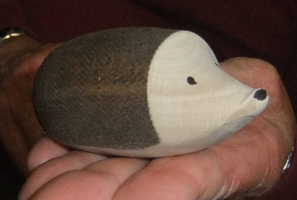
Paul had seen a picture of a hedgehog and thought he could improve it with an
up-turned snout using 'Off Centred Turning' principles and some 'Texturing' to
suggest a prickly coat.
(You can find both of these techniques described in our previous demonstrations
<HERE>)
When approaching a project where you have to work out the way of doing things,
it is likely that you will need to experiment on your first attempt. Paul
confided that the finished article he had shown at the start was his second
attempt and that he had adapted it from his initial plan.
HEDGEHOG
 He
didn't need a big piece of wood - he had selected a 100mm length of 40mm square
and marked diagonals on both ends. To achieve the eccentrical turning to come,
he marked the centre and a small offset up one diagonal with a larger offset on
the other side of the centre mark. He repeated this at the other end taking care
to mark the same offsets adjacent to the same side edge.
He
didn't need a big piece of wood - he had selected a 100mm length of 40mm square
and marked diagonals on both ends. To achieve the eccentrical turning to come,
he marked the centre and a small offset up one diagonal with a larger offset on
the other side of the centre mark. He repeated this at the other end taking care
to mark the same offsets adjacent to the same side edge.
The large offset would be used for the animal's underneath and one of the small
offsets would be used to form the face.
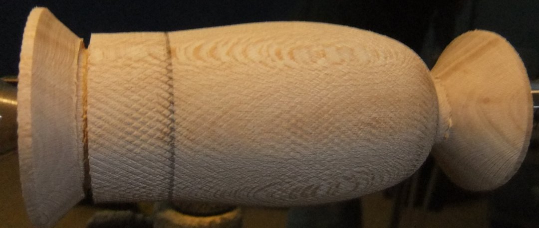
The Body
With the blank mounted between centres, Paul turned it to a cylinder
and then marked out the desired length of the hedgehog while ensuring that each
end had sufficient remaining wood to be strong enough to support the head and
tail drives for subsequent texturing and offset turning. He rounded off the back
end of the animal (without parting off) and tapered the face end.
It was important to sand before texturing because it would be impossible to sand
anything afterwards without spoiling the texture effect.
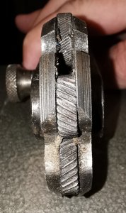
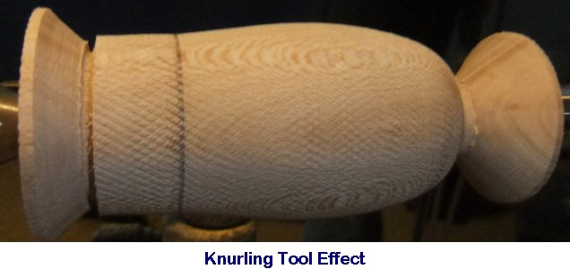
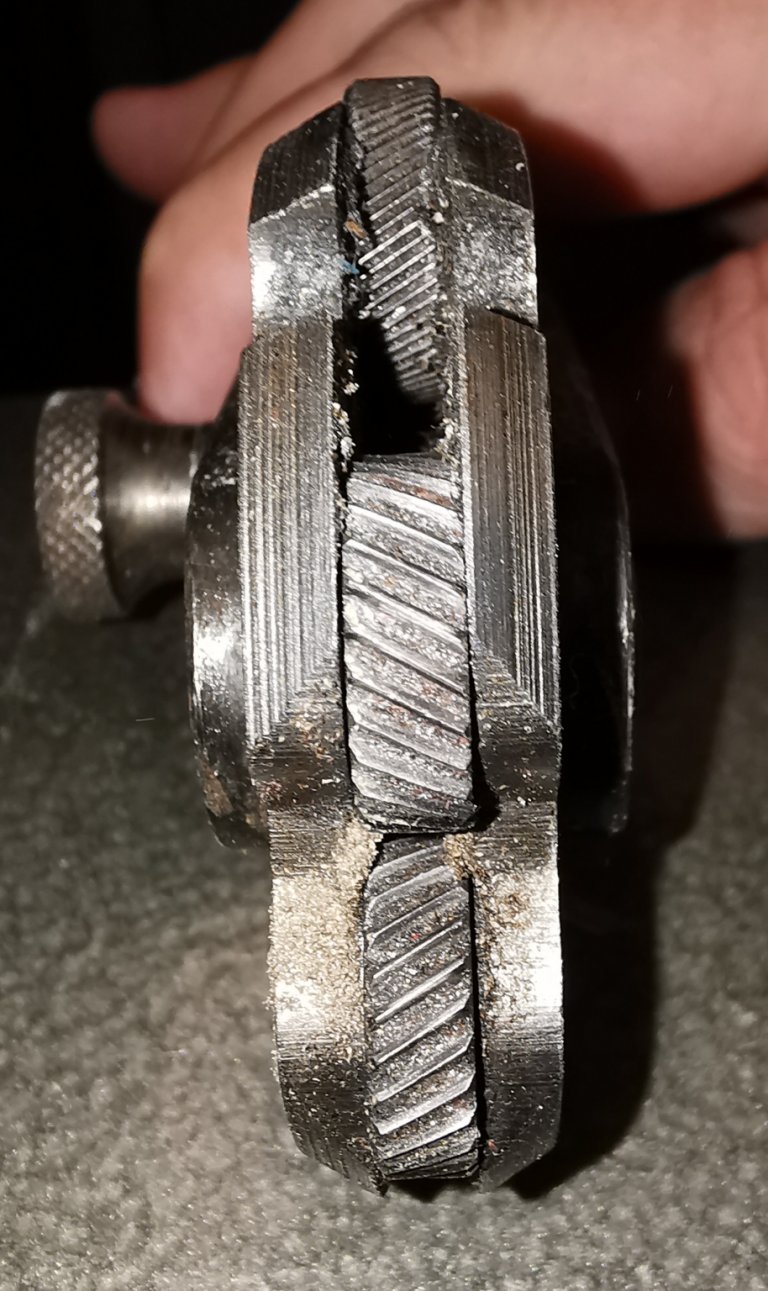
Paul's texturing tool was a
metal-worker's Knurling Tool (although similar could be achieved with others
available eg Henry Taylor Decorating Elf). To obtain the best result, Paul
maintained a positive inward force to keep an even pressure on the cutting
wheel(s) while the tool was moved along the tool rest making contact parallel to
the surface of the piece.
Paul finished the body with some appropriately coloured stain applied with a
cloth.
The Underneath
With the blank now centred on both large offsets AND checking by hand-turning
before starting that the piece cleared the tool rest, Paul started turning away
the hedgehog's underneath. This called for smooth movements because of the the
intermittent contact of the cutting edge of the gouge. The back and front ends
were rounded away but importantly, NOT turned away more than the central axis of
the starting cylinder (which of course is not the same as the central axis of
this current configuration). Paul's intention was to get the end of the finished
nose at the original central axis.
The underneath was then sanded with abrasives on a hard flat block held rigidly
perpendicular to the turning surface such that it only sanded the newly turned
surface without affecting the edge of the textured surface.
The
Face
The piece was configured with the headstock driving the central spot and the
tailstock holding the small offset at the hedgehog's face end. Paul turned away
the cylindrical wooden block end carefully so as to preserve the original
cylinder's central spot, which allowed better access to turn away a curved face.
This was sanded with a flat block as above before reconfiguring both stocks to
the original centres.
The tail and snout ends were turned away to almost parted. A Skew was the
preferred gouge to finish off the cross-grain ends to thin stubs, which were
then sawn clear.
The new cuts were tidied up with abrasives and fresh coloured stain applied to
the tail end.
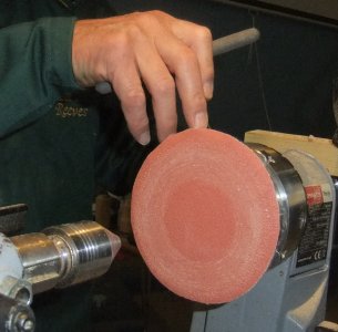
Paul set the headstock with a block holding an abrasive disc with Velcro in
order to put a flat on the underside to aid stability.

-----o00000o-----
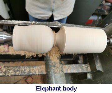
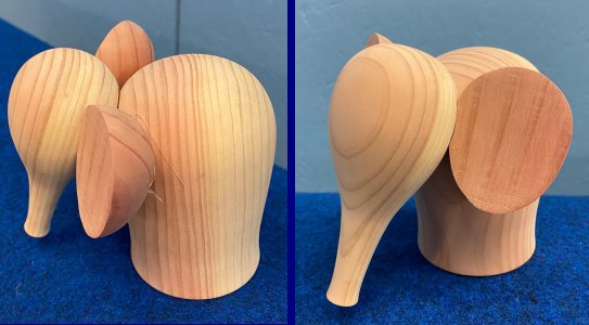
ELEPHANT
Another turned animal that caught Paul's attention was an Elephant, but very
much in a Scandinavian style rather than life-like. The design was clearly in 4
separate pieces connected together; possibly by dowels or perhaps by gluing
flattened bearing surfaces.
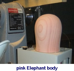
Inspired by the thought of a pink Elephant, Paul chose his recently planked
Redwood. This is a soft and slightly brittle wood so a ring centred tailstock
would be best.
The Head & Trunk
He had prepared the body prior to demonstration as it was a simple shape. Paul
felt the stylized head and trunk shouldn't touch the ground nor be much higher
than the body. He shaped and sanded before removing from the centres with a Skew
Chisel across the end-grain.
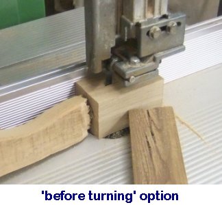
The
Ears
With an appropriately sized square blank, Paul had band sawed it in half and had
taped the halves together again with double-sided sticky tape applied to the
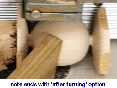
ends. (This can be done after turning but it helps to keep the ends square). Both drive and tail stocks needed to be ring centred types to avoid the
piece from splitting apart while turned to a centre. Having ridden elephants
himself while holidaying in Asia, Paul could vouchsafe that their ears were
quite triangular so he turned the cylinder into an oval shape before sanding and
then removing from the blank using a Skew. This resulted, after separating, into
a rounded triangular shape.
For assembly, he carefully checked
where the various components would need to be joined so he could then sand flat the
corresponding surfaces using the circular Velcro-holding disc above ready to be
hot glued together.
The November Competition was set for a
turned example of an animal as a stand alone piece
or
else on / in something relevant.
<Competition Results>
(photos by Andy Ogilvie, Rick
Patrick & Paul Reeves)
<to
index>
SEPTEMBER 2022
Taking on the
Kilner Challenge with
Andy
Ogilvie
Thu 15th
Sept at MWCC Club Night
As an enthusiast of being given a challenge rather than following someone else's
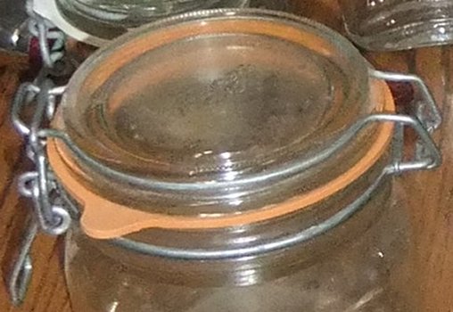
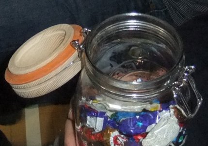
'recipe' of turning procedures, Andy accepted the 'Kilner Challenge' :-
To create an air-tight container like the renown Kilner Jar.
Following the standard plan of "Research -Theory - Practice - Refine," it looked
like he might fall at the first fence!
No amount of Google searching revealed anybody, anywhere able to supply the wire
hinges used by Kilner.
Neither could he devise a curved, hinged alternative made of wood; so his only
alternative was to cannibalize the wire hinge contraptions from an old Kilner
jar.
The closest he could find was that Asda had medium jars and clip top spice jars
on offer for £1.20 (as of Sept 2022).
It turned out that this was helpful as it became clear that whatever size of
hinge he used, it could not be adapted nor adjusted. Consequently, precise
dimensions at the bottom of the lid and at the top of the jar were required for
them to come together parallel and have any chance of the finished item being
air-tight.
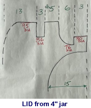
Before Andy started off turning wood, he prepared drawings showing all the
crucial distances & circumferences between the wires when closed, from accurate
measurements of his wire hinges 'stolen' from a 4" diameter jar.
These drawings were set and orientated correctly in his line of view from in
front of the lathe.
Andy had turned a lid and a base at home and found ways to refine the design
which he would highlight at the end of the demonstration.
Turning a Lid
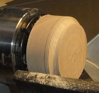
Andy had prepared a 4" square blank of Ash mounted in jaws and turned it down to a
95mm cylinder.
Working from his drawing and using an Outside Spring Caliper, Andy carefully
reduced the end 9mm to an 80mm diameter cylinder. (This could be achieved with
Parting Tool / Spindle Gouge / Skew - whichever preferred)
Using a thin Parting Tool and the Caliper, he turned a notch to a 76mm diameter,
which matched the internal diameter of the rubber seal (also cannibalized from
the Kilner Jar). This was subsequently turned back to the 95mm diameter as per
his drawing.
Similarly, a 3mm notch with a wider Parting Tool was turned to an 86mm diameter
at 11mm above the previous notch to accommodate the wire frame for the lid.
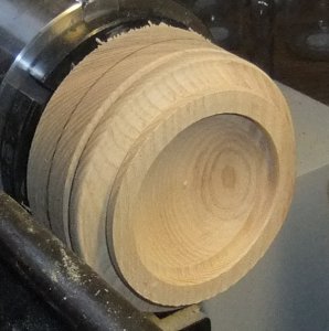
Next, the bottom of the lid was hollowed out while keeping in mind to keep the
resulting wall thickness strong enough to withstand any forces from the wire and
seal.
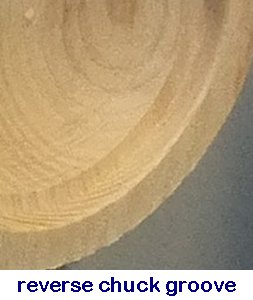
An appropriate groove was cut inside this hollowing to suit his chuck jaws in
expansion, which would be needed to reverse chuck the lid.
Finally, the top of the lid was rough shaped WITHOUT parting off.
The sides, notches & hollow were carefully sanded to crisp edges before reverse
chucking and finishing the lid top with gouge and abrasives.
The wire for the lid can be separated at the hinge and its loop be expanded over
the side of the lid before engaging the appropriate slot and re-engaged with the
hinge. Similarly, the rubber seal was fitted into its notch.
Turning a Base
This time,
Andy
used the seal and wire hinge from a 2½" jar for his demonstration.
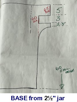
He
had prepared another drawing and a blank of Ash turned to a cylinder of 65mm and
with enough length to exceed 60cm depth of vessel.
The base was turned with the diameters, grooves, shaping and hollowing with
regular check-fitting of the base with its matching lid (turned prior to this
evening to save time) using the same method as described above for 'Turning a
Lid'.
The thickness of the walls at the base opening is most critical for strength at
its narrowest point (ie where the wire hinge sits.
Reverse chucking, shaping, detailing
and sanding carefully were completed as above.
Some thought should be given to which type of
finishing to use.
As the most common contents of these jars will be foodstuffs, a 'food safe' oil
or wax should be considered for at least the inside surfaces.
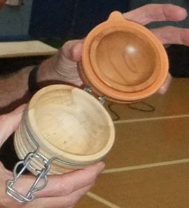
Refinements
Andy explained that his first wooden lid & base attempt for a single jar was
a design he subsequently rejected because it prevented the user to visually
identify the contents, whereas a glass jar is obviously not as limited.
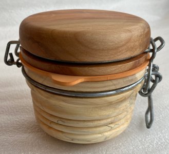
However, adding wooden lids to glass bases or wooden bases to glass lids
overcomes this limitation and certainly enhances their style.
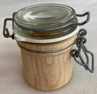
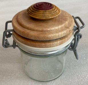
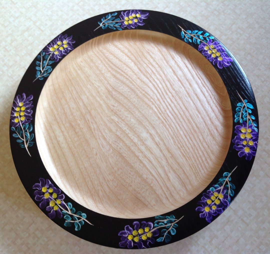
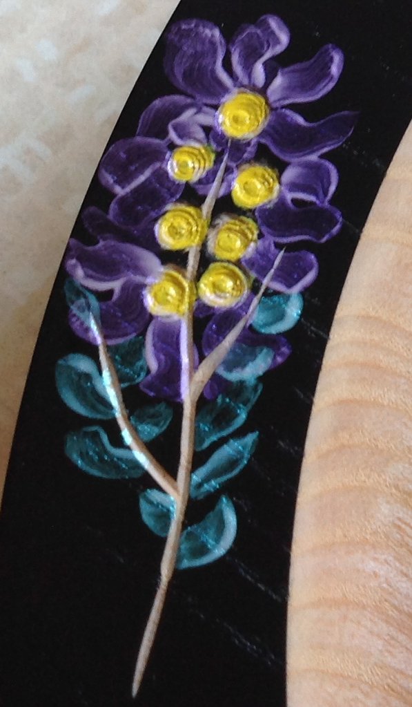
Another possible enhancement was by adding a
flower decoration, which Andy demonstrated after the tea break using Box with a
Purpleheart insert (shown above).
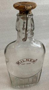
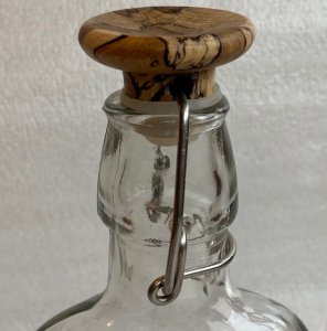
Finally, Andy produced a wooden top version for a Kilner bottle that he had made
at home to complete the Kilner range as well as his Challenge for the night.
<to
index>
August 2022 -
DEMO
3
Puzzles
& Tricks with
Paul Reeves
Thu 18th Aug 22 at MWCC Club Night
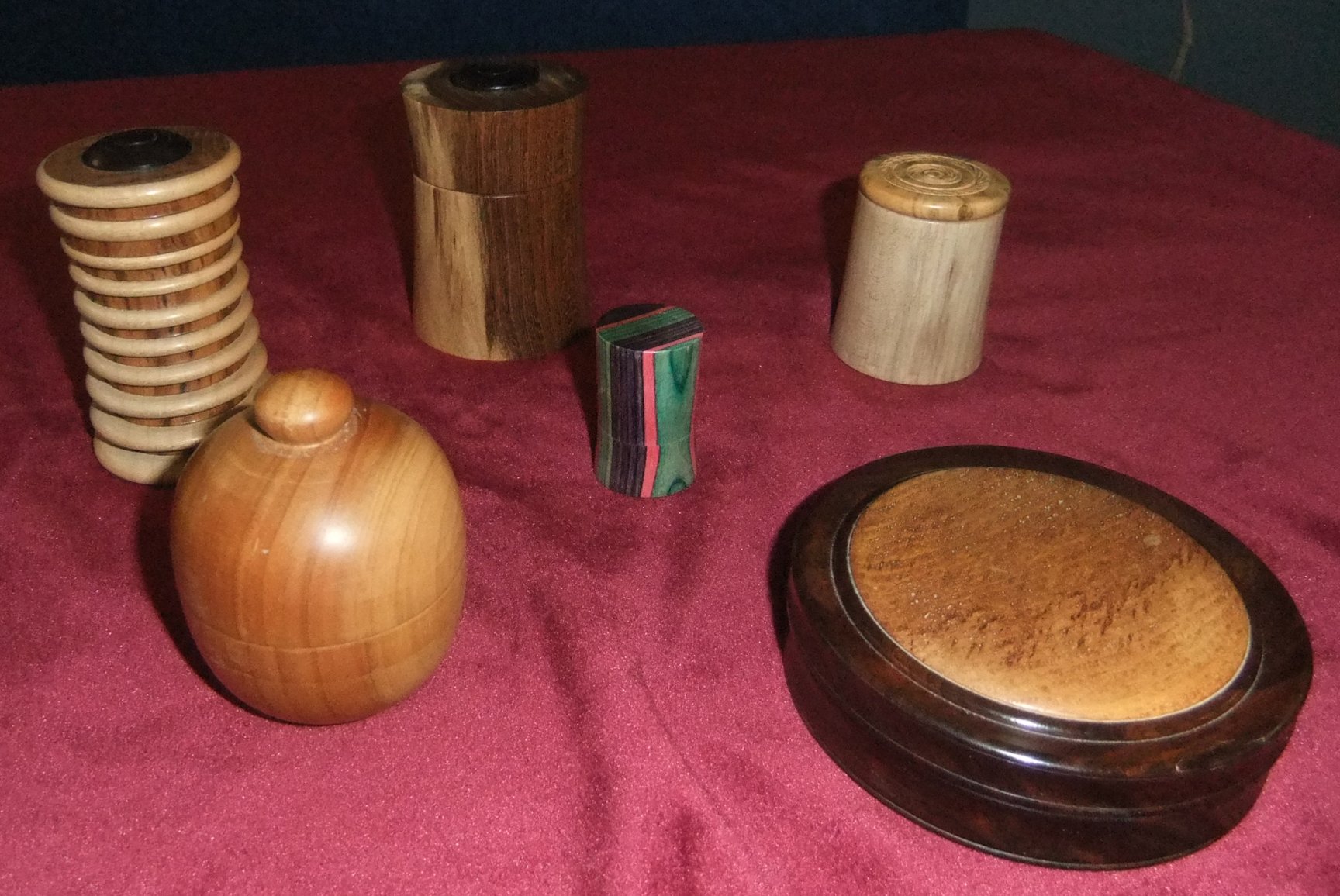
For clarity, games like Solitaire (although they
involve many turned parts) are not considered a puzzle in the sense we mean
tonight.
We are looking for a teaser that cannot be easily or readily solved.
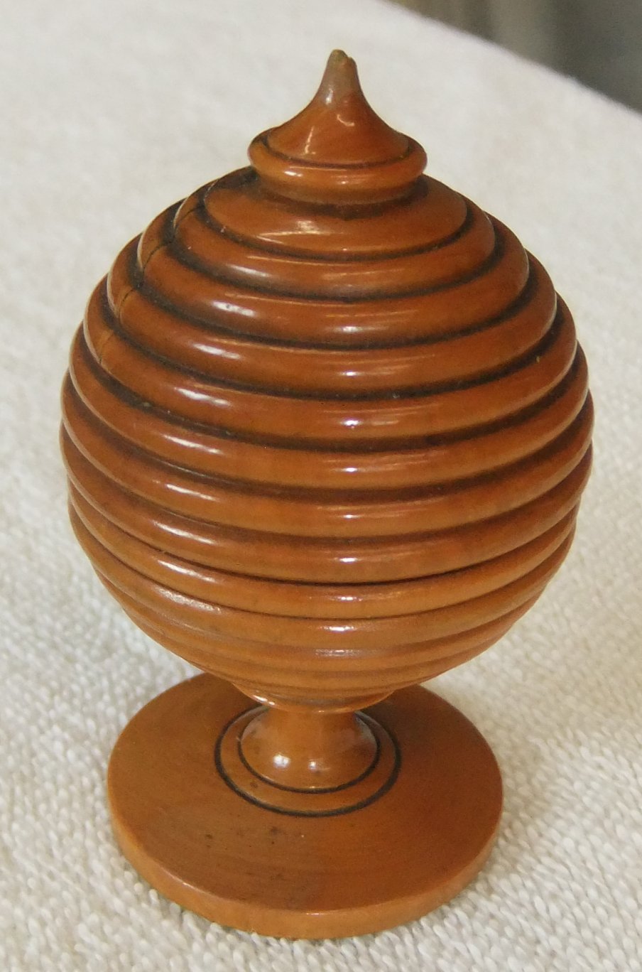
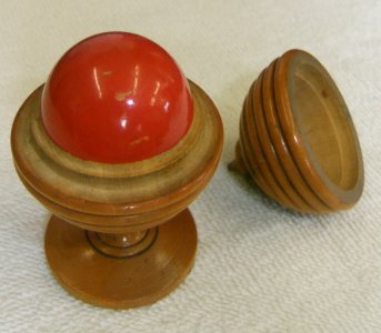
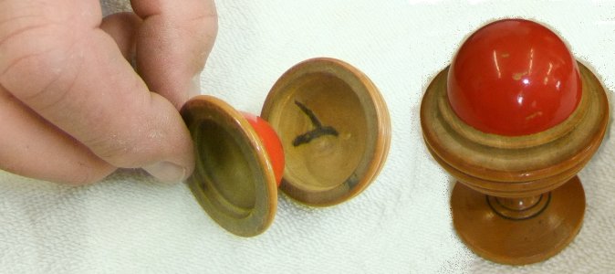
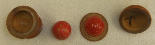
For example, Paul's Ball & Beehive puzzle with its apparently disappearing ball,
is a precisely turned piece with a very thin walled half ball within a segment
of a model skep (ancient straw beehive).
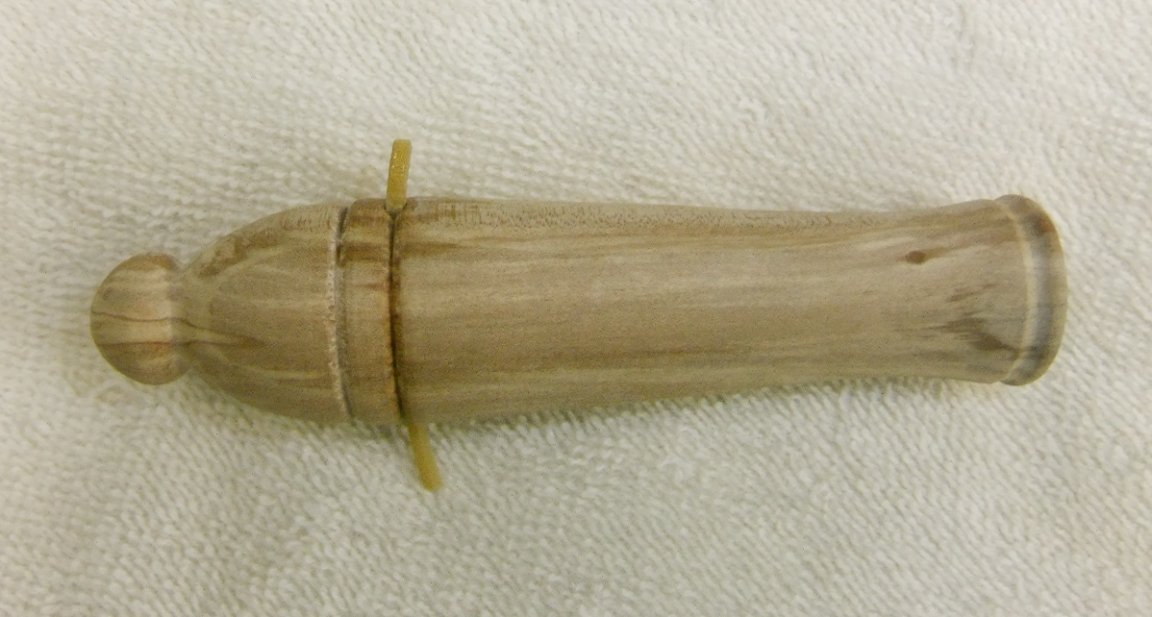
Lipstick Puzzle
The Puzzle Maker demonstrates to his
punter that the inner lipstick is able to slip out of its tube by turning it
upside down.
The task is to remove the inner lipstick without tipping it over. The stick is
annoyingly smooth, pointed and barely above the rim of the outer box.
 The skills required of the woodturner are to fashion the lipstick to a close fit
of a perfectly parallel inside wall of a box and at just the right height to be
unable to grip with fingertips. Also, as a contrast of colours appears more
striking, choose woods that have stood long enough to have stabilized their
moisture content and are of varieties unlikely to shrink/swell differently to
each other on dry/wet days.
The skills required of the woodturner are to fashion the lipstick to a close fit
of a perfectly parallel inside wall of a box and at just the right height to be
unable to grip with fingertips. Also, as a contrast of colours appears more
striking, choose woods that have stood long enough to have stabilized their
moisture content and are of varieties unlikely to shrink/swell differently to
each other on dry/wet days.
The best way to achieve the parallel wall is by using a drill held within a
Jacobs Chuck in your tailstock, (although if you don't have these tools
available, next best is a Box Cutter).
As accuracy of this cut is paramount and there can be a tendency for a drill to
'walk' on its first touch, you might consider using a Centre Drill Bit (aka Slocombe Bit) which are designed to provide a starting hole for a larger-sized
drill bit.
¤ The Box Section
Paul mounted a rectangular block clenched between the side edges of his
o'Donnell jaws and turned the exposed end to a cylinder of sufficient length for
the outer box.
A Jacobs Chuck was fitted to the tailstock and Paul selected an appropriately
sized Forstner bit with a toothed rim. Originally, a Saw-tooth Bit was used for
drilling down end grain and a Forstner Bit for cross grain.
The lathe was set to a slow speed and a hole was drilled to about 30mm depth.
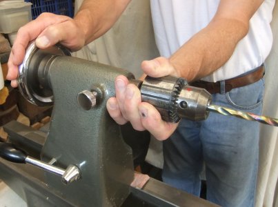 Top Tip
: When using a Jacobs Chuck, the
operation works well while under the positive pressure of winding the drill into
the piece but upon withdrawing, the bit can bind onto the inside of the cut hole
and get pulled out of the morse taper. Suddenly, a perfectly still drill chuck
with gear teeth has started revolving at the speed of the lathe. Anticipate this
by supporting the chuck to stay in the tailstock with your free hand gripping it
clear of the gear teeth.
Top Tip
: When using a Jacobs Chuck, the
operation works well while under the positive pressure of winding the drill into
the piece but upon withdrawing, the bit can bind onto the inside of the cut hole
and get pulled out of the morse taper. Suddenly, a perfectly still drill chuck
with gear teeth has started revolving at the speed of the lathe. Anticipate this
by supporting the chuck to stay in the tailstock with your free hand gripping it
clear of the gear teeth.
Having checked the depth of the hole, Paul marked
where he planned the base of the box to be with a narrow Parting Tool and shaped the outside to a thinner
body. He sanded through the grits on the outside and also, more importantly, the
inside using abrasives wrapped around a pencil.
To add interest, Paul used his Decorating Elf, brushing off resulting fluff
with a stiff bristle brush, used a Point Tool to define outlines and then a Taut
Wire to burn mark them taking care to keep the burn colour similar.
He parted off (still using double width cuts to avoid
jaming up his Parting
Tool) and then converted what was left in the jaws into a Jam Chuck to fit in
the drilled hole for reverse turning in order to finish the base.
He removed any centre pimple with a sharp Spindle Gouge or a shallow pointed
Skew, which cuts end grain very cleanly.
Paul applied decoration to match the sides although the circular burn marks had
to be done with a formica edge.
Finally, a touch up all round with abrasives, gently done to avoid any shrinkage
through sanding heat.
¤ The Lipstick
For a contrasting colour and lighter weight, Paul mounted a Sycamore blank as
previous.
Paul quickly turned it to a cylinder larger than the drilled hole of the box so
he could then carefully turn away the end with a Parting Tool, little by little,
regularly checking against the hole until the end could slide in & out without
any slackness.
He extended that diameter down the piece until further than the depth of the
box.
He used a Skew to turn the end to a point and at a slope that would leave the
cone shaped top reach full width below the lip of the box.
Paul sanded and decorated to match before parting off at a length that would leave the point just proud of the box,
Paul used the o'Donnell jaws to reverse mount the Lipstick and finish the
bottom.
The entire Lipstick was finally highly polished and placed in its box.
And the solution to the puzzle - blow it!
Providing there is a step down inside the lip of the box, a sharp puff will be
funnelled down the side of the lipstick and pneumatically raise it up and out.
(click for close up view)
The Sticky Ramrod
The punter is told of the importance of packing wadding tightly in a cannon and
that in Nelson's time, there was a device fitted to ensure the cannon would fire
its shot properly every time without misfiring. It used a rubber rope fitted
inside the barrel which the ramrod could hook up to and tamp the charge more
efficiently. Here is a scale model and this is how it works. The problem
was that only a skilled seamen could twist the ramrod the right way to make it
work. Let's see if you have what it takes to be a Master Gunner.
¤ The Cannon
Paul mounted a 5" x 1" block of Beech as above but supported with the tail stock
while turned to a cylinder.
With the tail stock withdrawn, the end was squared off with a shallow pointed
Skew.
The Jacobs Chuck was re-fitted and as the end cross-section was quite small, Paul elected to
start with a Centre Drill Bit before using an 8mm twist drill to bore a hole
almost to the end.
Paul turned the
outside to the shape of a ship's cannon.
A tiny hole was drilled on each side opposite each other just short of where the
internal bore ended so that a string of rubber could be threaded through and
glued at the holes.
The cannon was sanded, decorated and the back end (the Cascable) was
turned before it was parted
off.

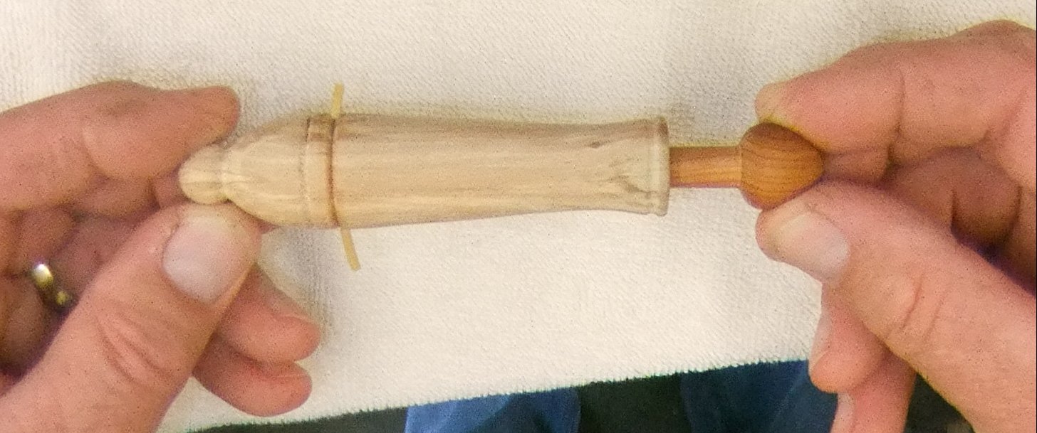
¤ The Ramrod
A dense piece of Yew was mounted between his o'Donell Chuck and the tail centre to
make a stick in the shape of a ramrod.
Using a Roughing Gouge to start and a Parting Tool with an Outside Spring
Caliper for turning the diameter away with precision, Paul turned the blank to a
cylinder with 3 sections (evenly spaced out) having been carefully turned down
to just under 8mm but keeping a cylinder of wood at each end.
The Roughing Gouge was then used to turn away the wood between the 3 sections.
As the piece was getting quite thin, Paul rested one hand on top of the piece
immediately above where the gouge was cutting. This allowed him to lightly
press against the upward force of the gouge tip cutting the wood.
Each ramrod end was shaped as shown in the photo below before being well sanded and
parted off.
The distance between the cannon lip and the rubber was measured and a notch was
made on the ramrod at a position where it would engage with the rubber string
before the rod was fully in the barrel. Finally it was touched up all round as
necessary and highly polished.

(click for close up view)
And the solution to
the puzzle - it's like squeezing a slippery lemon pip.
The rubber string is a red herring - after the glue had hardened, a drill bit
was shoved up the bore and broke it so there is nothing for the notch to catch.
When the Puzzle Maker demonstrates his 'skill', he pulls the ramrod out as if it
had resistance and by subtly squeezing forefinger against thumb, the ramrod will
fly out of his fingers and smack back into the bore; all due to the end shape of
the ramrod.
The September Competition was set for a
Puzzle or Trick incorporating elements of turned piece(s)
<Competition Results>
<to
index>
June 2022 -
DEMO 2
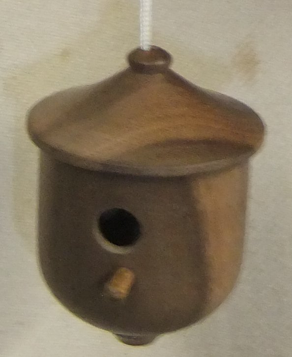
 Bird
Box
with Paul Reeves
Bird
Box
with Paul Reeves
Thursday, 16th June 2022 at MWCC Club Night
You might have previously turned a Christmas Tree ornament in the shape of a
bird box, but to turn one of full size would waste a lot of wood, unless you
started with a log.
 (click for close up view)
But before that, it is worth researching expert advice on sizes, designs and
finishes.
A good place to start is from the RSPB <here>
Leaving aside where and how to attach your bird box, some thought has to be
determined about external & internal sizes before mounting your chosen log.
Apparently, the rougher the finish, the better for the occupants.
Inside walls must be rough enough for chicks to grip when they try to go for
their first flight.
In times gone past, a perch was invariably incorporated but isn't any longer as
they tended to be perfect for predators to lay siege on the nesting tenants.
 Paul had considered making a box out of staves and bound like a barrel but
decided upon a relatively straight log just over 6" in diameter. He had
started at home on a Graduate lathe because it was large enough to prepare the
body and roof with the log as a single piece.
Paul had considered making a box out of staves and bound like a barrel but
decided upon a relatively straight log just over 6" in diameter. He had
started at home on a Graduate lathe because it was large enough to prepare the
body and roof with the log as a single piece.
If you have a smaller lathe similar to the size of the Club's, then you will
need to saw the log into the two component parts and prepare them separately.
Whichever method you use,
■
Mount the piece(s) between centres;
■
Leave one half of the roof section untouched to ensure that the bottom of the
roof will be bigger than the diameter of the body - this will allow the roof to
sit below the top of the body and avoid rain getting inside;
■
Create a spigot on the bottom of the body section and another spigot on
the top of the roof section to fit any reasonably large
and deep jaws that you have for your chuck.
Paul's Leylandii log had been a victim of February's Dudley & Eunice storms. It was
tight for the RSPB suggested dimensions but their sizes were suited for a
rectangular box whereas Paul's was for a circular box, which after all is a more
natural shape for a nest.
Shaping the Body
The body section was then mounted using the freshly turned spigot in the selected
sturdy jaws and the outside was trimmed up with a Roughing Gouge.
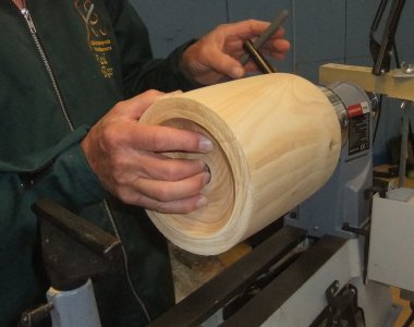
(click above for close up view)
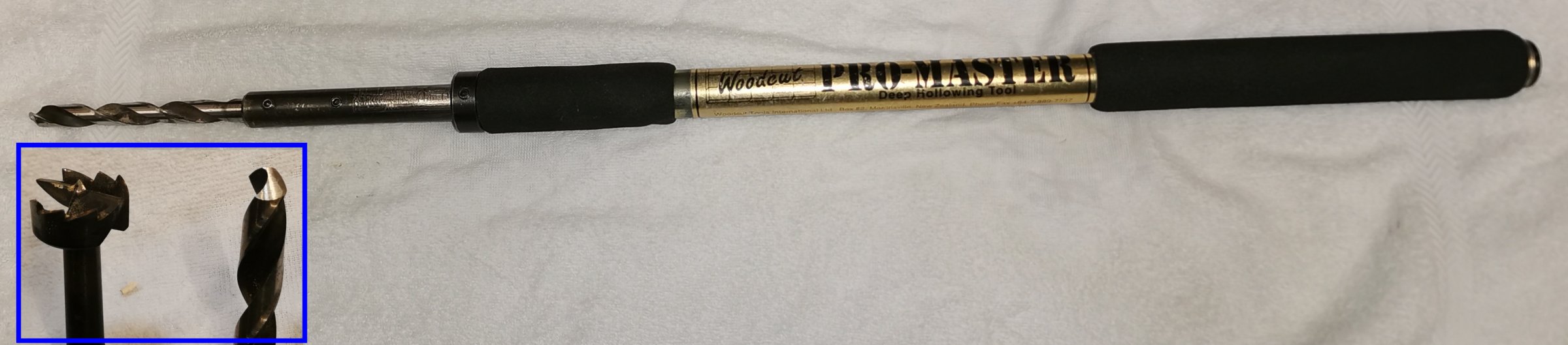
Next, the centre was bored out with a Woodcut Pro Master Deep
Hollowing Tool which could secure Twist Drills Bits and Sawtooth Bits with grub
screws. Paul did try using a Sawtooth Bit initially with a toolrest
helping to start the central bore-hole accurately, but he found that it soon got
clogged with soft wet fibres so changed to a twist drill bit. Once the
central hole had been started, the toolrest was moved out of the way because the
rotating mounted piece kept the tool handle steady while the twist drill
progressed precisely down the spin axis centre. The hole
would eventually go through the entire body and out the bottom to act as a
drain but because of the limited length of the drill, this had to happen in
stages as the inside was hollowed.
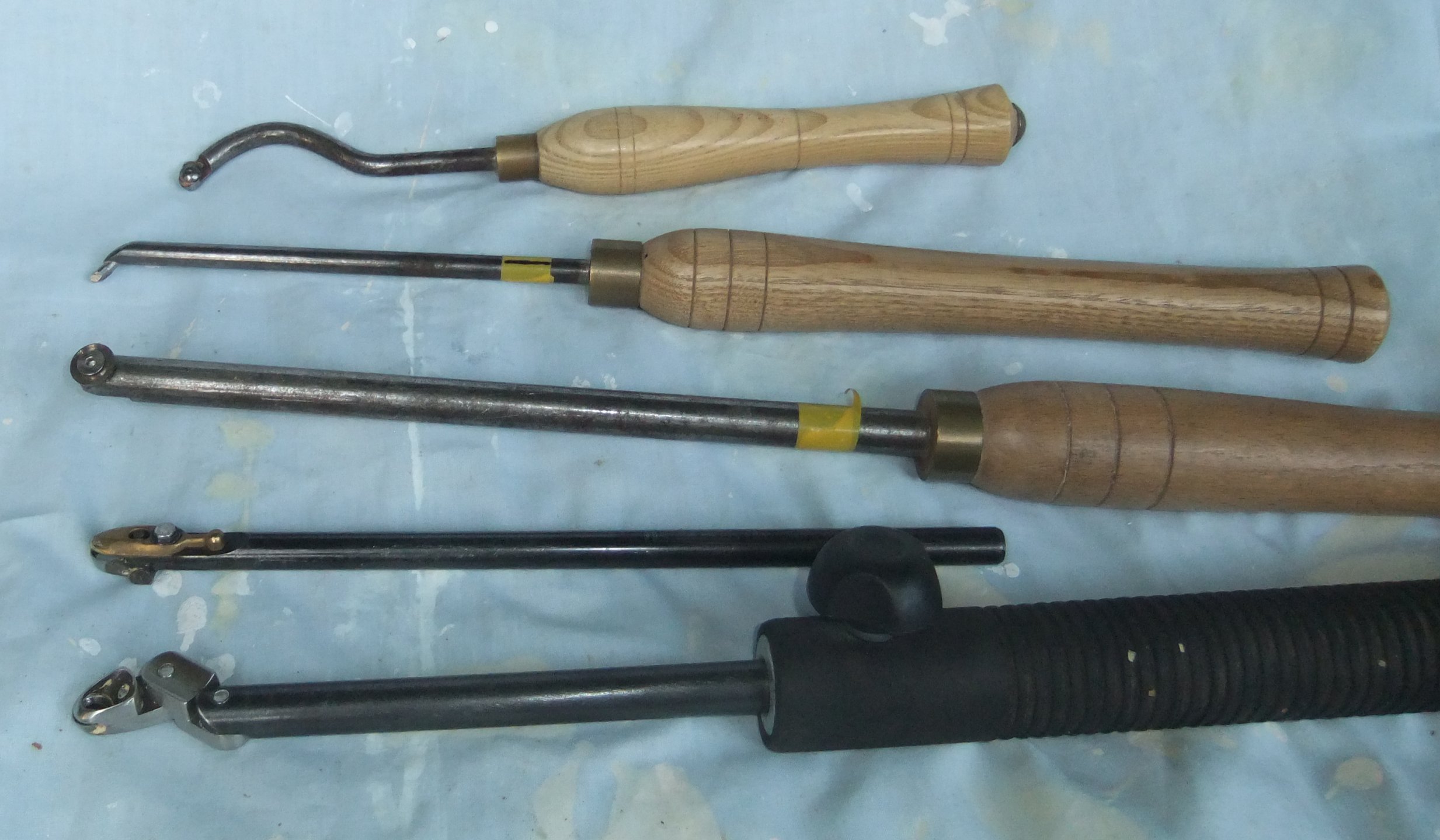
The body was now ready to hollow out to the determined diameter & depth.
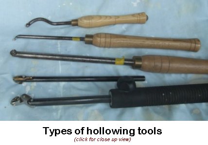
From the photo above :-
the top 2 are 'pick' tools which are easier to control but work rather slowly
because they produce small shavings;
the middle is a 'tip' tool which handles similarly as the pick tools but
slightly quicker;
the 4th is a Woodcut Pro Forme with the brass cap acting as a bevel;
and the bottom is a Rolly Munro articulated hollower. The bottom 2 do a much
quicker job but need practice to work efficiently.
There is one other option not shown above but had to be employed before these
specialised tools came along - a hefty Spindle Gouge used very gingerly and
taking a long time to complete the job.
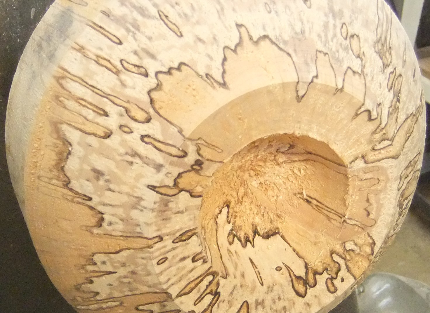
Paul selected the Rolly Munro and started hollowing from the
centre outwards.
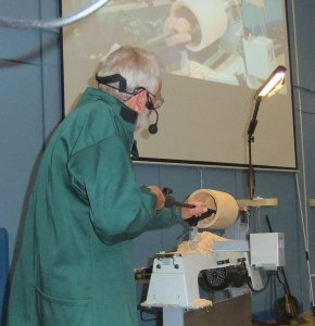
Ordinarily, one would aim to avoid producing vibrations and keep the cutter
running evenly to maintain a smooth finished surface, but the inside surface
needed to be a little rough, so hollowing out was progressed at pace.
Paul's technique was to have the tool handle pinned between his body and under
his arm while using his body weight rather than arm muscles to keep the tool
level with a consistent cut.
As the depth progressed, the ideal ratio of 5:1 either side of the toolrest
wasn't possible so his left hand needed a strong grip to hold the tool down onto
the rest.
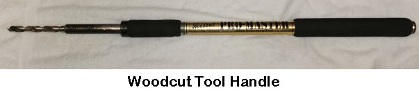
Also, it was important not to lose the central hole. Because Paul hadn't
managed to breach the bottom of the piece earlier, he returned to his Twist
Drill Bit once he had hollowed out enough to allow the Woodcut Tool Handle to go inside the
body without touching the sides. Eventually, he managed to extend the central
bore right through the spigot to form the drain hole.
Knots can block the tool head with poorly cut shavings and need to be cleared
immediately as they prevent the cutting edge from working. He continued to
his planned depth and rounded off the inside floor like a natural nest. Having
checked for even thickness of the walls, he used a Spindle
Gouge on the outside and turn a curved bottom to match the inside shaping.
Having determined the size
and position of the hole as guided by the RSPB advice sheet, now would be a good
time to drill the entrance, although Paul had done this before the
demonstration.
(click above for close up view)
Shaping the Roof
This project is a great exercise for just getting on with the shape
as there is no worry about the resulting smoothness or finish.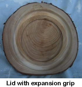
The roof section was mounted using the prepared spigot and Paul levelled off the
base.
He had decided to create a dome in the centre and incorporate a recess to fit
the current chuck in expansion.
Having marked the required chuck diameter with callipers, he used a Spindle Gouge
starting from inside and carefully cut out to the mark. He finished off with an
angled scraper to match the dovetail of the jaws.
Then he used the callipers
again but this time set to the external diameter of the completed body and marked another circle in the roof's base and cut as above so that the
Bird Box body
could be inset into the roof.
He used a Parting Tool to enlarge and square off the inset
rebate to a close
fit.
These shavings were dusty as he was now scraping end grain.
This now allowed an opportunity to reverse turn the Bird Box
body and finish shaping it's rounded bottom.
With the roof still mounted and the body pressed into it's rebate by the tailstock
pressing against the newly drilled drain hole, you could turn away most of the the spigot and
shape the bottom of the body, before removing from the chuck and chiselling off the remnant
hollowed stub.
The roof was turned around and mounted into the newly cut expansion recess.
Top Tip : After cutting a
recess for an expansion dovetail, nearly tighten the jaws and hand turn the
piece - this will help clear out the bottom of the groove and allow the piece to
be held perfectly square.
The roof not only keeps the nest area dry;
it can also be designed to deter predators e.g. a spiked minaret!
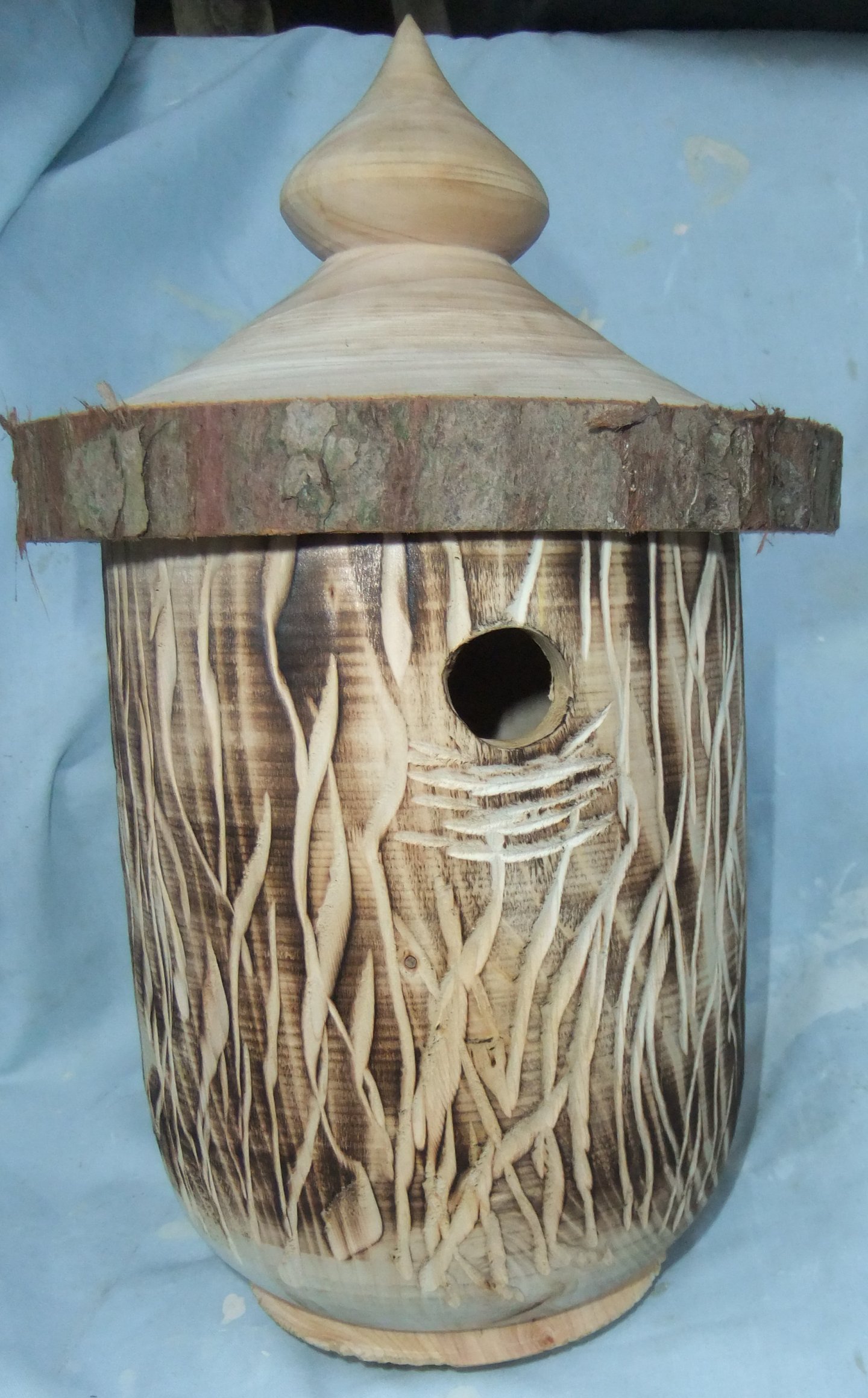
Finishing the Outside
As recommended by the RSPB, apply any finish to the outside only.
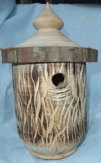
Paul wanted to leave the roof as turned but disguise the body by 'scorching'
then using a Proxxon Long Neck Angle Grinder with a Carving Disc.
He used a blow torch to lightly blacken the body
(executed outside the Fire Exit in order to avoid setting off the Hall's
alarm!).
As the piece had to be removed from the lathe, a sensible precaution was to wear
an appropriate glove on his hand in front of the flame.
The Proxxon carving tool looks intimidating but isn't when handled with respect
and a bit of practice.
With the piece secured in the chuck, one hand held the
body of the grinder while the other hand remained on Paul's side of the
cutters, either switching the motor on/off or supporting the other hand or
rotating the chuck.
When switched on, the rotation of the cutters will be trying to move the grinder
away from your body.
Paul's technique was to just gently stroke the wood while pulling the grinder
towards himself using just the corners of the teeth to cut.
If this is your first attempt with a carving cutter, it is probably best to
practice on scrap wood before attempting on your hard worked piece. You might
find it helpful to control the motion of one hand by supporting it
with your other - rather than have both hands gripping the tool.
The first cuts Paul made were horizontal just below the entrance hole to give
something for birds to grip upon landing. He specifically made the horizontal
cuts angled downwards so any water would drop away rather than collect in the
groove.
The rest of the cuts were vertical.
(click for close up view)
The July Competition was set for a Bird Box turned piece(s).
<Competition Results>
<to
index>
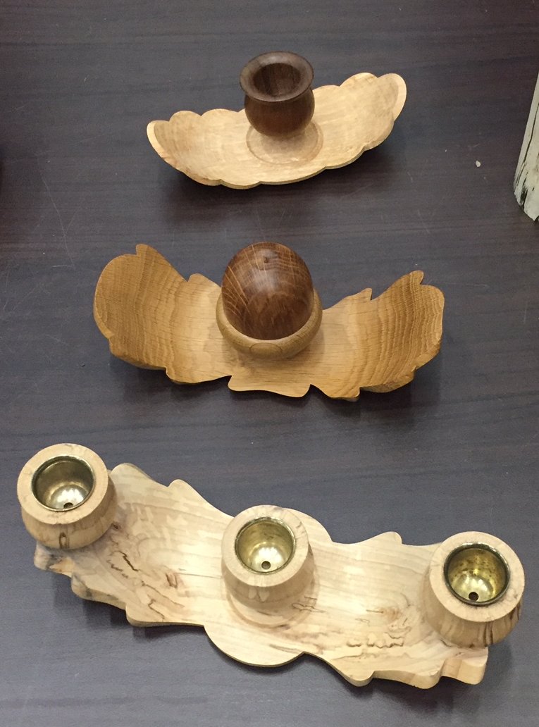
April 2022 -
DEMO 1
Unnatural Natural Edge
with Paul Reeves
Thursday, 21st April 2022 at MWCC Club Night

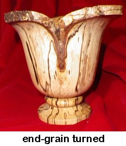
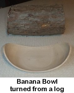
Natural Edge pieces rely upon the outside parts of the tree to improve
the final look of the turned piece, whether it is by retaining the bark or
stripping the outside edge to the Cambium Layer as seen in the Banana Bowl
below. The latter's often unexpected shape is produced by turning a log
'end over end' as if you were making a two-bladed propeller.
An
Unnatural Natural Edge is when
the edge has been 'embellished' prior to turning the intended piece.
 (click for close up view)
These shapes can be achieved by first turning
between End-Grain centres (like a spindle) to create an outside shape, a tiny
part of which will become the edges of the piece when subsequently turned 'end
over end'.
Individual Method.
A log was turned into a cylinder and the
ends were squared off.
A pencil line was drawn down the length of the cylinder and its midpoint
circumference marked.
Top Tip : Now is an opportunity to draw
the pencil line so that any flaw on one side of the cylinder will be part of the
wood turned away from the finished piece.
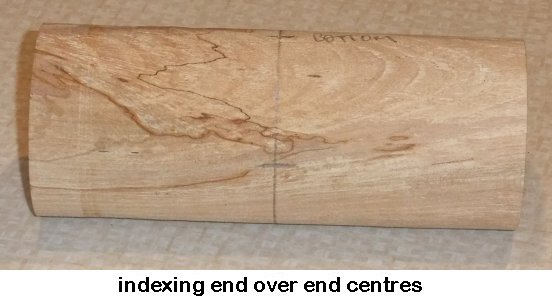
Then the point 180° opposite was found using either the index of the
lathe/chuck; alternatively if your lathe hasn't any indexing, then by carefully
extending the pencil line through the end-grain centres and down the opposite
side so that the opposite centre will be found where this new line intersects
the previously drawn midpoint circumference.
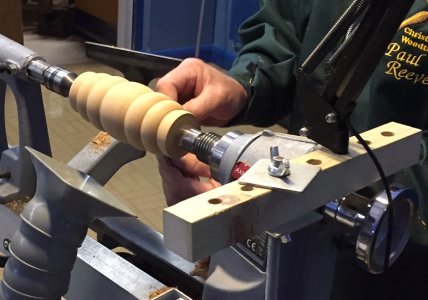
With the cylinder still being
in/returned to its end-grain centres, a profile was turned into the sides.
Ideally, the shape should be a mirror image either side of the midpoint
circumference and avoid any sharp outward points as these are vulnerable to
breaking when turning end to end.
The shape was sanded through the grits as it will be the finished edge of the
final piece.
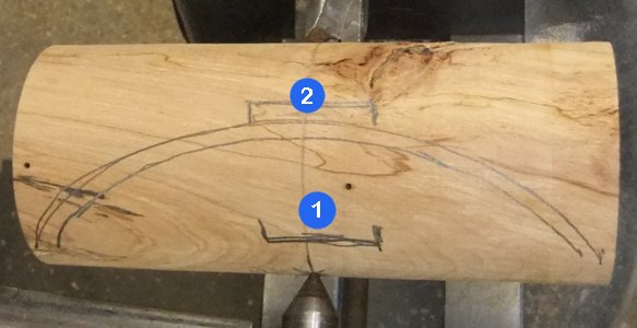
The piece was now mounted
between the end over end centres previously marked.
The photo below shows the planned outline for two spigots to be turned
The inside spigot (labelled ❶
in photo) is the first to be formed while between centres.
Then with that first spigot being mounted in a chuck (and if you feel necessary,
the opposite side being supported by the tailstock), turn away the outside to your desired shape while
creating the second spigot ❷
to where the base of the piece will be.
Top Tip : With the shape formed, sand
through the grits with a flat block held vertically so that it only touches the
wood perpendicular to its surface; this will ensure all leading edges will
remain crisp.
The piece was then reversed so that the base
spigot (labelled ❷
in photo) was now mounted in the chuck.
The piece was hollowed out to match the finished outside shape by carefully
maintaining an even thickness down the length of the profiled edge. Get
the thickness of the edges furthest from the centre accurate before progressing
inwards in order to maintain strength & integrity while working on the outer
wings.
Eventually, the inside spigot will be either turned away or shaped to
accommodate an embellishment (eg a candle holder; a box).
The inside surface should be HAND SANDED carefully to keep all edges crisp.
Reverse chuck to remove the remaining base spigot and to create a base/foot.
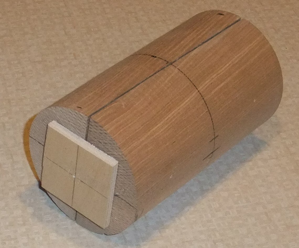
Pair Method.
Sometimes you will want to create a matching pair of intricate edged pieces.
This is easily accomplished with two identically sized rectangular blocks.
Paul's happened to have two 6" x 3" x 1½" Ash blocks, which he hot glued
together to result with a single square ended block of 6" x 3" x 3".
He then hot glued plywood squares marked so that they could be mounted exactly
on the centre line of the combined block before turning between centres to a
cylinder.
Then as above, a midpoint circumference was drawn followed by two opposite
points for the end over end centres, but this time, of course, both had to be
90° from the glued joint.
 (click for close up view)
Again as above, your chosen profile
should be turned into the cylinder; avoid leaving sharp points (unless very
dense timber is used).
Sand to a finish before taking apart the ends and glue joint, and divide the
cylinder into an identical pair of rectangular blocks.
Once the centres of the
resulting flat rectangular surfaces were marked, repeat the end over end turning
guidance described above <click here to find>
Factors
to Consider
►Lathe speed
is important - the faster the better in order to decrease the time
the tool is turning 'air gaps' (although speed is limited by any imbalance of
the piece);
►Move the
tool in a controlled smooth curve and allow the rotation to do the cutting;
►Don't
press the bevel onto the wood - else you will end up pushing the
tool into the 'air gaps' and the leading edges will become damaged.
The May Competition was set for an Unnatural Natural Edge turned piece or
matching pieces.
<Competition Results>
<to
index>
MAY 2022
Revision of
Bowl Turning Techniques
with Paul Reeves
Thursday, 19th
May 22 at MWCC Club Night
It seems that the general public believe all woodturners are able to turn
bowls so the expectations upon us are great. However, there is a lot to
take into account before you even pick up a bowl blank.
POINTS TO CONSIDER :
■ Use of Bowl - Decoration normally
gives added value but best avoided if
to be used
with liquid / food as it will be difficult to keep any grooves clear and clean.
■ Material Choice - a Fruit Bowl can be made of almost anything because it's
not necessary to be food safe whereas a Salad Bowl is restricted to non-porous,
non-tainting & non-toxic woods. So avoid Ash /Laburnum / Padauk / Purpleheart
/ Yew
etc and
stick to woods like Maple / Beech / Sycamore / Tulip Wood / American Plane etc
that are considered to be food-safe.
■ Size & Shape - Deep will hold a lot but not ideal for holding delicate
objects heaped up on one another. Open like a platter is good for showing off
what is there but a high-sided or undercut bowl edge is better for tossing
salads.
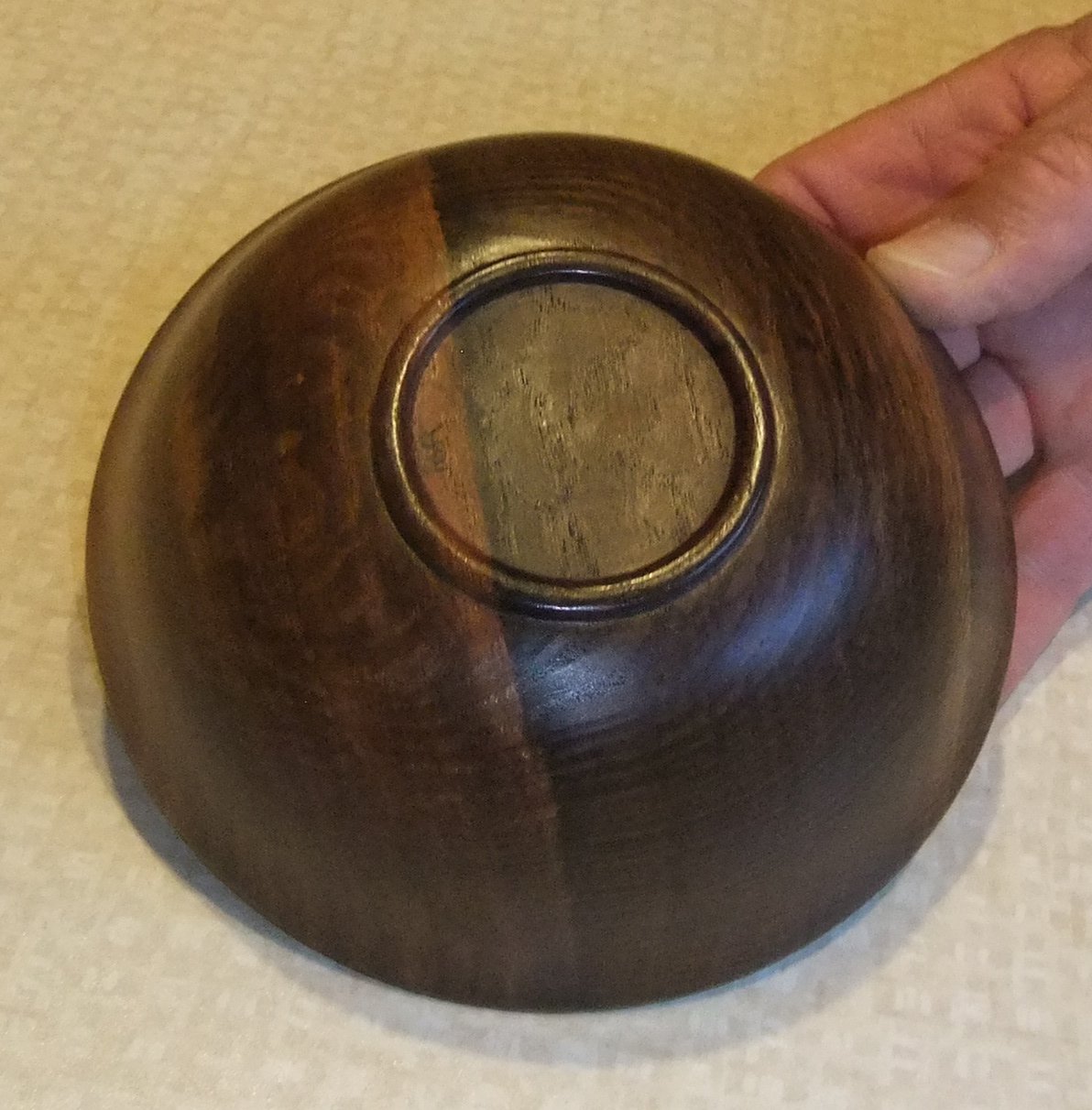
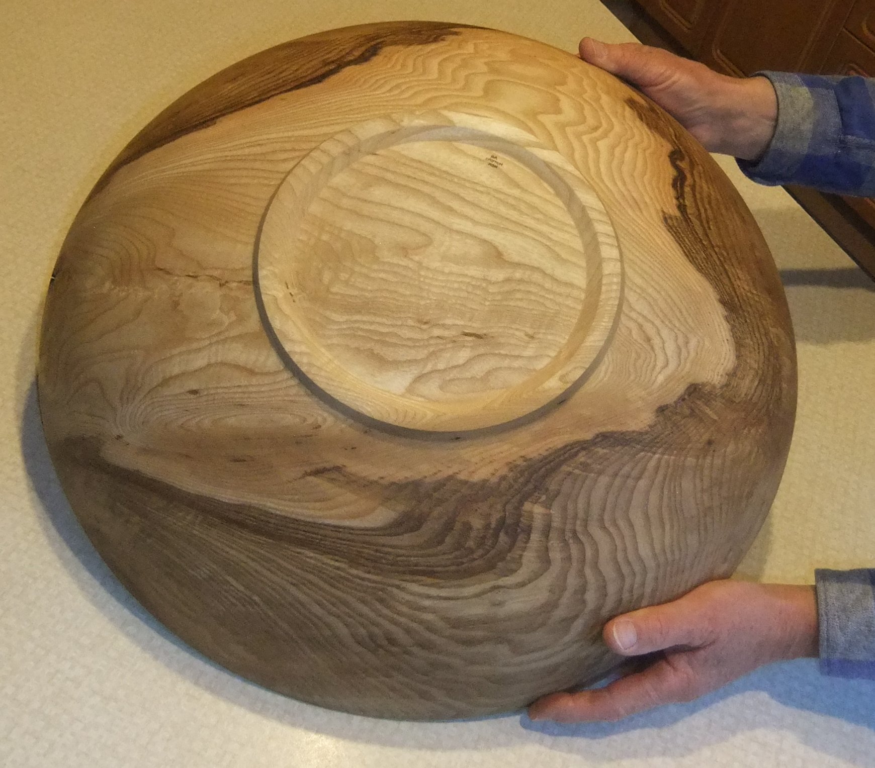
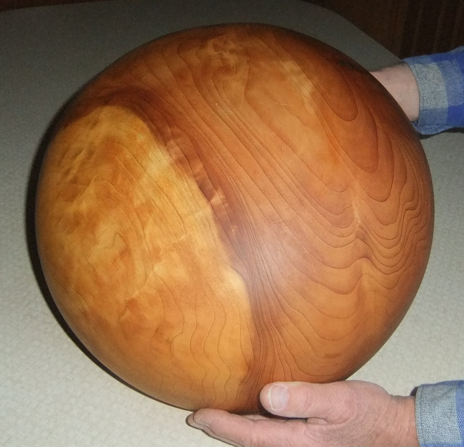
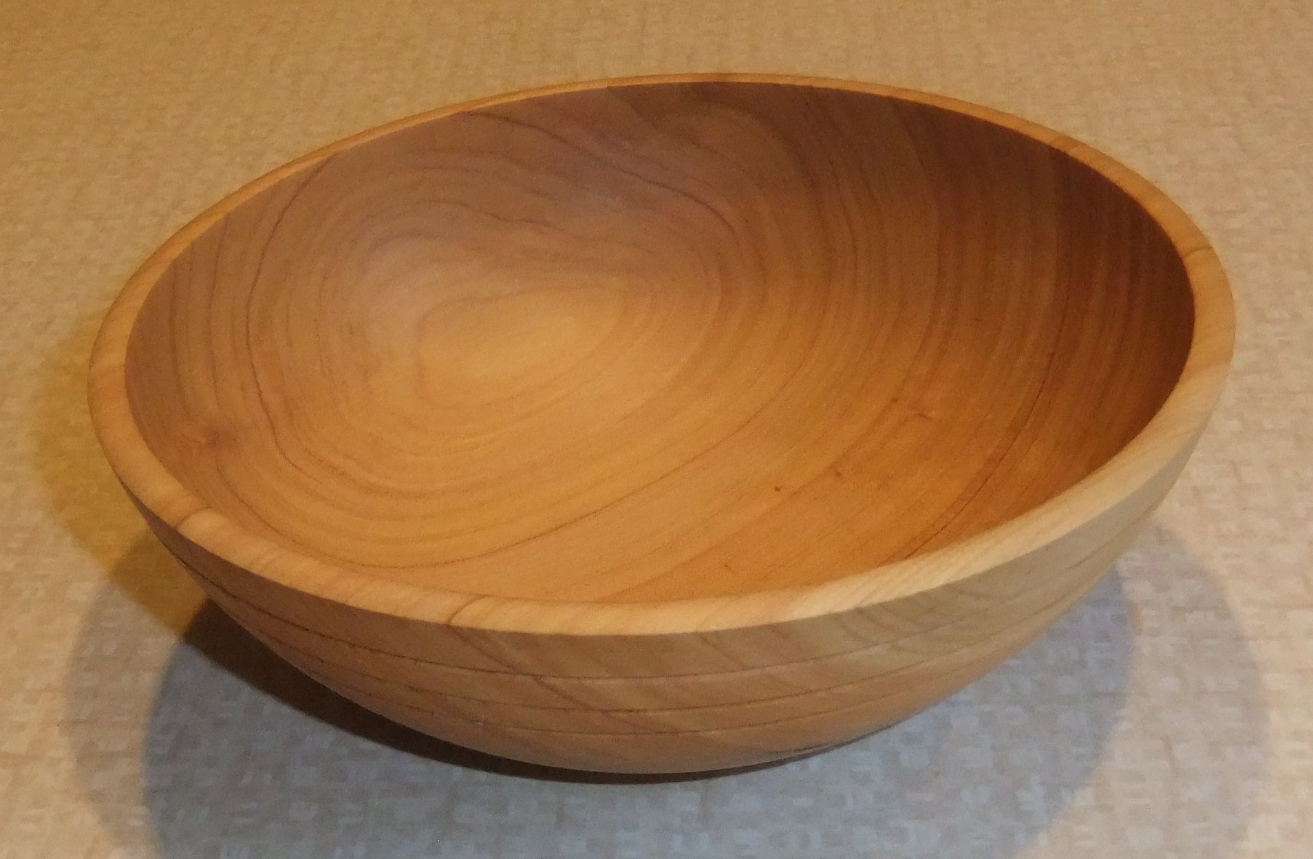
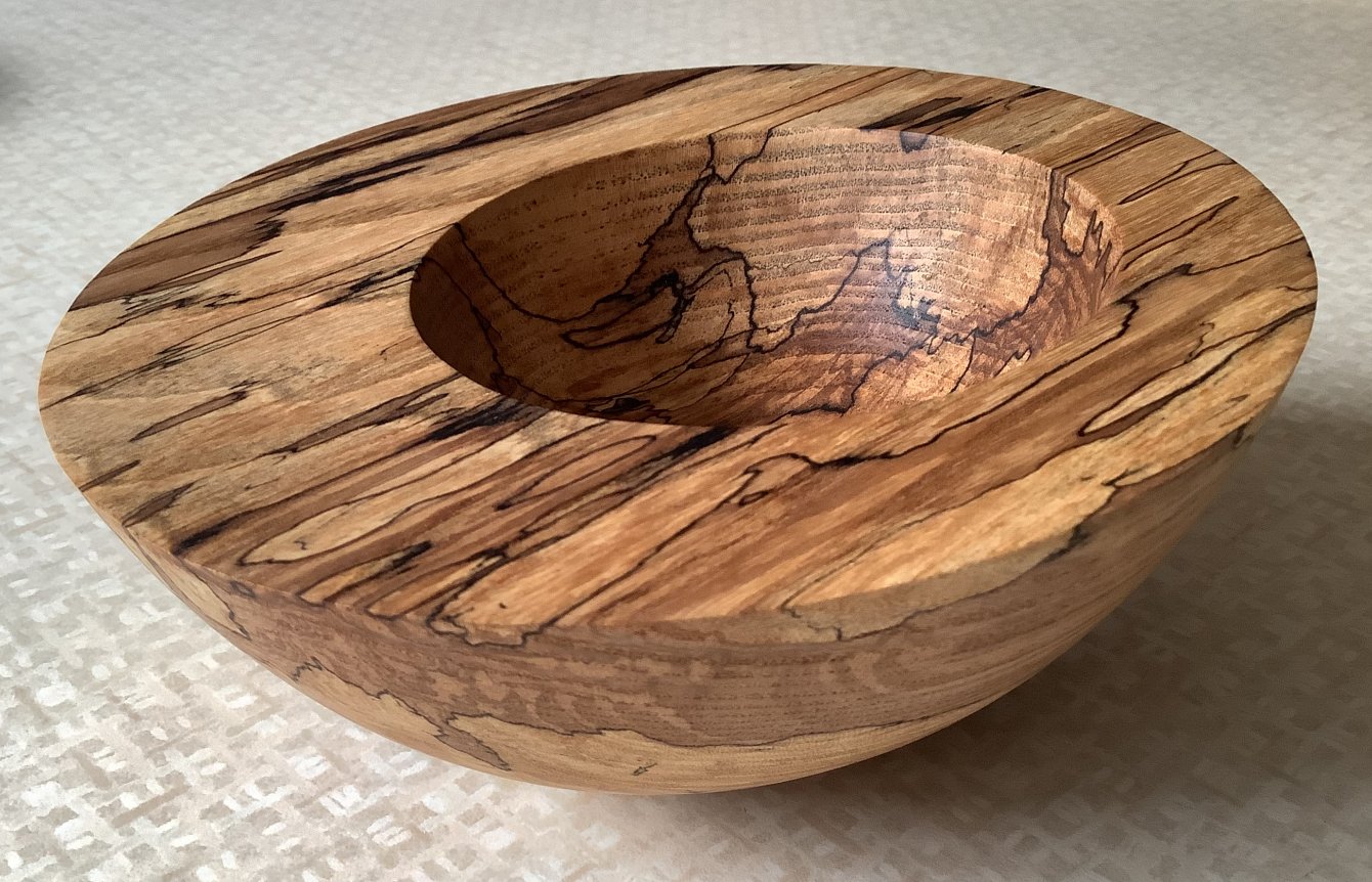
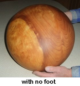
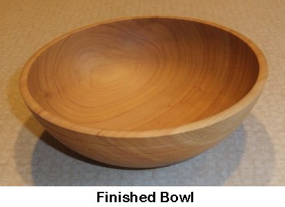
Paul had selected a 7" by 3" Macrocarpa bowl
blank to highlight that although it can tear a lot when turned, with sharp
tools, a clean thin walled example can produce a sturdy bowl like the one he has used for years to keep
the
family's keys tidy.
Macrocarpa is a coniferous tree endemic to California
where it is known as Monterey Cypress and also prolific in New Zealand after
introduction in the mid 19th century. It is denser than most
pines and more resinous which gives off a smell for a long time before it dries
out. But once dried, it is very durable and holds shape well even when turned to
a thin walled vessel.
■ Mounting on Lathe -
Having decide which end would be the base after a look for figure / faults, he
mounted the piece on the lathe using a screw chuck. (An alternative could have
been between centres)
Because he was using a flat plate screw chuck held within jaws, he bevelled the
pre-drilled hole in the top surface to prevent any scurf created as the Screw
Chuck bit a thread into the blank, which could have prevented the piece from
being held flat against the chuck's plate.
■ Tail Stock - Whether to use a tail stock to help support the piece would depend upon how
big the blank was and whether you were going to take deep cuts like a 'Show
Pro'! This was a small blank and there was sufficient time to take
measured cuts so leaving the tail stock off allowed Paul better access to the
piece.
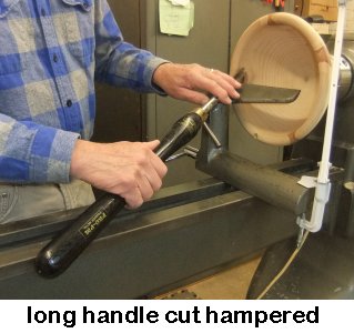
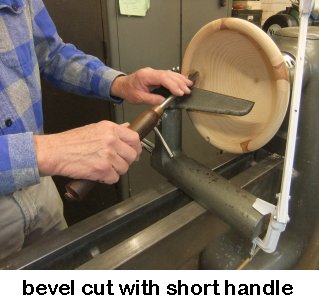
■ Choice of Gouge - A Bowl Gouge is the
obvious answer but how long should the handle be? If your drive head is
fixed and you are not using a Tail Stock, then a short handle is better in order
to avoid being hampered by the rails. However, some lathes have drive heads that
can be slid towards the end of the rails to emulate a short bed option, which
can accommodate long handles.
■ Choice of Cuts - The gouge can be used as
a 'Push Cut' (produces a clean bevel finish) or a 'Pull Cut' (results in
deeper/quicker removal and gets closer to the intended foot but gives a rougher finish).
A Pull Cut needs careful technique as only the radius of the curve and a little
of the wing should be in contact to generate a controllable cut. This is
achieved by presenting the bevel parallel to the wood surface with the flute
facing towards your left shoulder to ensure the wing is supported.
Providing your tool rest is close enough to the curved surface, you should be
able to start with a Pull Cut and by rolling the front radius of the gouge, you
can turn into a Push Cut within one smooth pass.
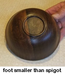
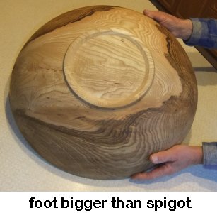
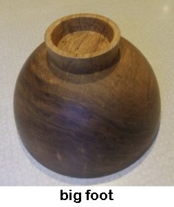
■ Plan the Foot - Don't let the chuck decide
the size of the foot. Big bowls need a foot outside a spigot for standard jaws.
The foot position will influence the chuck jaw mounting for hollowing with
regard to whether a 'compression' spigot (needs depth for a good grip) should be
created or an 'expansion' dovetail (reduced depth required but must have enough
wood strength outside the dovetail). You could decide upon no foot, but is
prone to rock. Once decided which jaws to use, set
your dividers to the appropriate size and remember when scoring the base, only
the LHS point touches the work - the RHS point must only touch air.
■ Squaring off Spigot/Dovetail - When
turning a bowl (except with an end grain bowl blank) there is often a problem
cutting across the end grains and ending up with fluffy strands which can hinder
the jaws from holding the piece centrally. Parting Tools and Skew Chisels
don't work as well as a small Spindle Gouge which will 'cut' the end grain
rather than scrape across them. A sharp gouge and moving the tip
slowly across the surface will also help.
■ Tools to Help Shaping - Shear Scraper
using a straight cutter for external and curved cutter for inside shaping. Lead
with the handle and angle the cutter against the wood surface away from being
horizontal.
■ Finishing - Mark the spigot's centre
point before detaching from the drive head to aid eventual reverse chucking removal. Sander Seal all
end grains and any tear-outs near faults before making your final pass with the
gouge. Try to move from start to end without stopping.
■ Decorations - Lines and marks can be made
with any SHARP pointy tool but avoid going too shallow as they might disappear
after sanding. Burnishing marks with wire tend to vary intensity when passed
over cross grain then end grain but Formica Burnishing is much better.
■ Abrasives - Beware getting your work
too hot while sanding with the piece turning. Some woods (eg Yew, Macrocarpa)
get hot from friction very quickly and can end up cracked. This danger is
reduced by slowing the lathe speed and by regularly keeping the abrasive clear
of dust build up with a wipe across a piece of carpet.
With the outside surface finished and sanded, Paul took the piece off the
screw chuck and set up the chosen chuck jaws to grip the prepared spigot.
He then squared off the face with a combination of pull & push cuts with the
Bowl Gouge.
■ Shape of Inside - Lots of options
:- a small hollow in the centre; match the curve of the outside; curve the rim;
undercut the rim.
■ Direction of Cuts - For an Outside
Curve, cut from the axis of spin towards the outside. (NB: you often have to cut
a small area the other way in order to get a clean corner up to a spigot /
foot).
For an Inside Curve, cut inwards from the rim towards the axis of spin.
With a gouge with a swept-back grind, you have to steer the gouge tip above the
horizontal in order to avoid the metal bar of the gouge crashing into the rim but must steer back to end the cut at the spin axis. If
the bowl is particularly deep or has an inside curve with a sharp change of
direction, use a Bowl Gouge with a large bevelled angle (eg 70°) to help get a continuous
cut from rim to centre.
■ Tip Control - Be aware that until
the bevel can give support, the gouge tip has a tendency to slip outwards when
starting the cut. This is alleviated with a positive control of the gouge bar
where it lays on the tool rest and of the handle in your other hand.
As your cut moves towards the centre, the rate of the turning wood passing the
tool tip reduces so you should slow your movement as the tip gets closer to the
spin axis.
Try not to interrupt your cuts as it will spoil your 'muscle memory' for the
final cut. Make sure you have a sharp gouge before you start and get the
thickness of the bowl's wall uniform and accurate well before the last cuts.
There is an argument for making that last cut large rather than trying to skim
in one movement. This will lead to a cleaner cut and less angles to try to sand
out.
Angle the tool rest into the hollow to reduce the amount of gouge over-hanging
as it sweeps around the inside curve.
If the bowl is to be thin walled, work on getting the inner surface near the rim
close to the desired thickness before working further down the bowl. The extra
thickness in the bottom will discourage the thin walls from flexing during your
cuts.
With the inside sanded, it was time to reverse the piece in order to remove
the spigot and finish the foot. The first thing Paul measured was the thickness
at the bottom of the bowl. This confirmed how much of the spigot could be
removed.
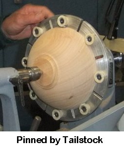
■ Reverse Chucks - There are
several ways to hold the piece for the next job.
Use an MDF faceplate with a groove cut into it to exactly fit the diameter of
the rim OR Press the piece against a flat faceplate while holding it
in place with the tail stock in the pockmark previously made when forming the
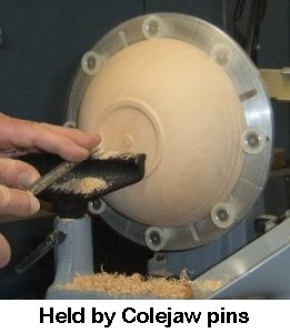
spigot OR Colejaws;
Whichever method is used, nibble the spigot away with a Spindle Gouge cutting
inwards towards the head stock - if you try cutting across, the same problem
with fluffy end grain will arise.
Paul had chosen to use Colejaws, so he protected the surface of
the rim with some masking tape before putting the piece in and tightening the
jaws.
Now that he knew how much he needed to remove from the base, he deliberately
left a pimple at the centre to give an accurate gauge of the depth removed and
then cut it away with the last cut.
<to
index>
FEBRUARY 2022
Demonstration of
Sphere Turning Plus
with Paul Reeves
Thursday, 17th February 22 at MWCC Club Night
Spherical shapes are predominantly used in games and for decorations.
If a large number of same-sized wooden balls are required (for
example a solitaire
set) then purchase from an eBay supplier might be the quickest, most economical
and accurate method rather than making them yourself. (Feb
2022 price for 50 of 20mm diameter beech wooden balls = £10).
But a perfect sphere is not always necessary. For example, a ball used in a
coconut shy needs to be more robust, dry and stress-free than be perfectly
round.
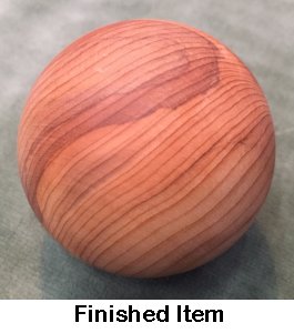
For a decorative ball in natural finish then a perfect sphere would be
preferable and the choice of wood should be something interesting; for example
burr or figured or chatoyant.
The 'Plus' element is referring to starting with a ball and then enhancing by
carving, hollowing out or colouring.
In fact, you don't even have to start with a ball.
There are several options to turn your own sphere :-
Buying a Ball-Turning Jig - expensive
Roughly turning with a round cutter -
difficult to control
Rubber ring chuck with a rubber ring tail stock -
inaccurate if rubber flexes
Wooden Cup Chuck method
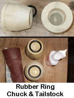
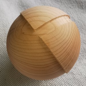
Paul demonstrated using the Wooden Cup Chuck method.
A rectangular block of Yew had been prepared with it held between centres and
turned to an even cylinder.
 He set an External Caliper to the diameter of the cylinder (which would become
the diameter of the sphere). With this set Caliper resting approximately
centrally on top of the cylinder, he marked the two ends of the Caliper with a
pencil and then with the aid of the tool rest, drew two pencil lines around the
cylinder to mark the extent of where the edges of the sphere would be.
He set an External Caliper to the diameter of the cylinder (which would become
the diameter of the sphere). With this set Caliper resting approximately
centrally on top of the cylinder, he marked the two ends of the Caliper with a
pencil and then with the aid of the tool rest, drew two pencil lines around the
cylinder to mark the extent of where the edges of the sphere would be.
Using a ruler, he calculated and marked another circle around the cylinder half
way between the previous two lines. This circle became his starting 'meridian',
which from now on, SHOULD NOT be cut any smaller (although
might end up being so later to correct errors!).
The two sphere edges had to be kept clearly defined with a Parting Tool so that
the outer edges of the sphere wouldn't get lost.
A spindle gouge was used to turn a curve like a giant bead which started at the
untouched centre meridian and would have eventually ended vertically at the
centre of the wood but for Paul refraining from completely parting through.
As the curves progressed, Paul had to return to using the Parting Tool in order
to prevent losing precisely where the ends were going to be.
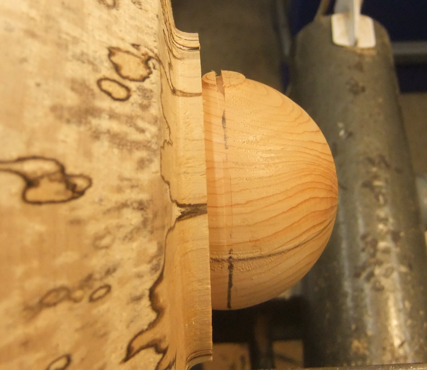
Once he had reduced the attached ends to about 5mm (and
the curves not quite yet vertical), Paul stopped the
lathe and after taking the pressure off the tail stock, used a saw to detached
the approximately shaped sphere with 2 small stubs at opposite ends.
Making a Cup Chuck
 End Grain is preferable as it is less likely to distort into an oval shape as
the wood moves with age/humidity. A softer wood than the object wood is also
helpful.
End Grain is preferable as it is less likely to distort into an oval shape as
the wood moves with age/humidity. A softer wood than the object wood is also
helpful.
With a suitable blank mounted between centres, turn a spigot at one end to fit
your lathe chuck.
Then with that lathe chuck fitted and holding the spigot of the Cup Chuck,
square off the face and drill/gouge a hole down the centre in order to help
hollowing out.
The hollow across the face should be fractionally less than the diameter of the
sphere but definitely deeper than its radius to avoid the sphere from 'bottoming
out' when fitted into the cup.
Should you inadvertently hollow out the width too much, then further squaring
off will reduce the diameter because of the bowl shape of the hollow - but
remember you might need to deepen it further to avoid bottoming out.
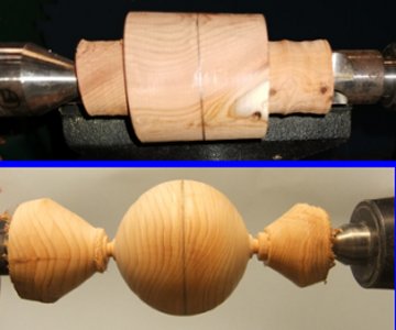
Working with the Cup Chuck
Fit the sphere into the cup with the starting 'meridian' at right angles to the
face of the chuck. A slap with the palm of your hand should result in a good
grip provided the two small stubs from the previous turning do not protrude too
much.
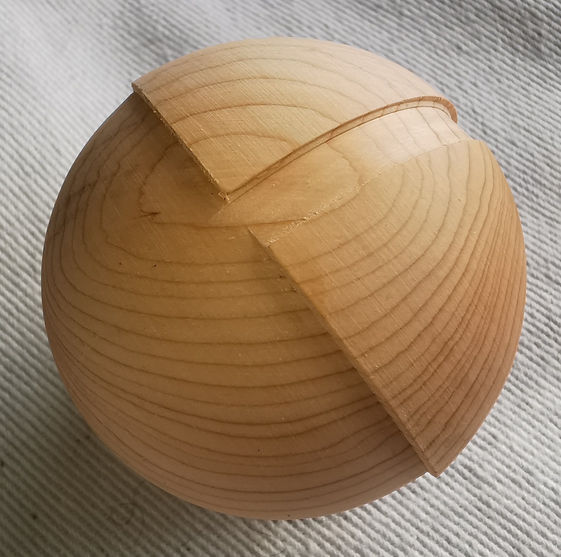
The aim now is to use a narrow Parting Tool to create another meridian just deep
enough to match the depth of the starting meridian at the 2 points where they
intersect.
To achieve this, increase the lathe speed, then very VERY gingerly move the
narrow Parting Tool inwards so that it gently nicks the stubs. Stopping to draw
a pencil line along this new meridian will help to judge when your depth is
enough. Continue to gently part away until the pencil line almost disappears
before stopping and checking the depths where the meridians intersect. Repeat
until the intersections are of matching depths.
A Spindle Gouge can then be used to turn away any excess above the two
meridians. Move the tool rest so that the gouge bevel can touch the rotational
axis point or 'pole' where the surface will be perfectly level and therefore no
buffeting vibration will be sensed through the gouge when the lathe is turning.
However, once you move away and come across something higher than the meridians,
you will feel, hear (and possibly see) the tool buffet.
The next steps require precise and delicate control of the gouge tip.
Slide the bevel back sufficiently for the gouge tip to reach where the buffeting
started and allow the tip to just cut some dust; then carefully and steadily
move the tool forward to cut away a very thin layer; stopping if the tool starts
to run smoothly. Backtrack using the bevel and test for buffeting. Repeat the
delicate cutting until the buffeting dissipates. Smoothness can be assessed
with a light touch of the surface at the top of the piece with your thumb
pointing towards the direction of rotation.
Once this hemisphere is nearly even, a straight edged skew can be used to gently
smooth out any bumps sensed by your thumb, but keep the tool's contact moving at
all times.
When satisfied, slow the lathe speed down and briefly sand with abrasives. If
abrasives are used too much, there is a likelihood that more surface will be
removed on the side-grain than the cross-grain sides resulting in the sphere
appearing pointed.
The abrasive can be hand held or used with a flat block, but in both cases keep
the abrasive moving and parallel to the point of contact.
Next, the sphere was removed. It might require a mallet to tap the Cup Chuck in
the direction towards the head stock, but be ready to catch it when it pops out
with the first tap. (Do try to avoid hitting the sphere of course!)
The sphere is reversed to tackle the remaining hemisphere.
However, the Cup may be too large for the previously trimmed hemisphere so a
quick squaring off the face of the Cup Chuck as described above will narrow the
opening. Remember to check if the bottom of the hollow needs deepening.
Repeat as above to remove all the surface that is standing proud of the
meridians.
Short use of abrasive and your sphere will be complete.
<to
index>
January 2022 -
DEMO 5
Added Value
to a
Two-Part Candlestick/Lamp
with Paul Reeves
Thursday, 20th January 2022 at MWCC Club Night
The basics of two part turning was covered in
Spindle & Face Plate Turned in January 2020
with a three-legged stool. <available HERE>
This time we are turning a candlestick/table lamp with "added value".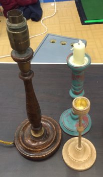
Some examples are shown in the adjacent photos :
●
A Victorian Table Lamp with a shoulder at the top, elegantly turned and enhanced
with gold colour highlights.
●
A plain wood decorated with a base coat beneath a top contrasting coat, which
was wiped before drying to expose the base colour in places.
●
A slender column enhanced with a knop (ornamental rounded protuberance) painted
or conjoined with a different colour or wood type.
●
Paul's oversized candlestick with its added value of a large piece of copper
plate, which doubled as a fire precaution as well as the spiked seat for the
large candle above.
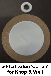
This demonstration is a Table Lamp with the added value of alternative
embellishments, e.g. Corian.
(Corian is a man-made mix of minerals and acrylic typically used in worktops and
can be turned on the lathe with a scraper.)
Top Tip : As synthetic materials tend not to move with
humidity, best to select dry wood for the wooden parts of the piece to avoid
loose joints when it inevitably shrinks inside a home.
Paul is using some surplus Corian-like material that had been
developed for aircraft interiors; however it can be worked the same as Corian.
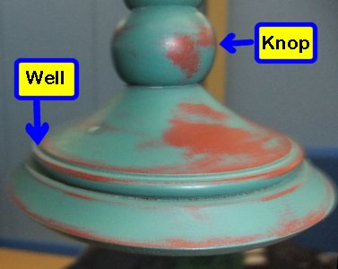
The Knops.
There were to be decorative rings at the bottom & the top of the stem.
To save time, Paul had initially used his bandsaw to cut out a circular piece of
his material at home (surprisingly, the bandsaw had no problem cutting an accurate
circle on these types of synthetic material). He had then mounted the resulting
disc within his chuck jaws and drilled a central hole of a size suitable for a spigot (soon to
be turned on the stem so it would fit securely into the base).
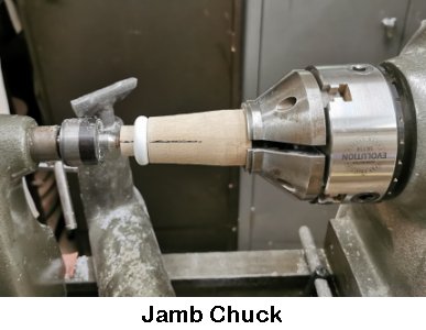
Next he created a Jam Chuck from a cylindrical piece of gash wood such that one
end could be secured in his chuck and the other end reduced using a
Parting Tool so that it just fitted into the hole of the Corian and had a clean
cut shoulder to hold the Corian perfectly square. He carefully made an accurate
saw cut through the centre mark of the working end (down to well below the shoulder line)
using a band saw or a tenon saw. With the the Jam Chuck attached to the head
stock and the Corian ring set against the shoulder, the tail stock was tightened
with its tapered point gradually parting either side of the saw cut until it
jammed the Corian fixed onto his chuck.
Corian doesn't have any grain so it has no problem being scraped into a bead
with virtually any piece of well honed metal. The scraper works best with a
negative rake and by keeping it moving while at a slower lathe speed than when
turning wood.
Paul scraped one half of a bead and squared off down to the Jam Chuck on the
tail stock side of the piece before sanding. Corian sands well but does need the
lathe slowed even further while keeping the abrasive clear and cool by brushing
a carpet against the grit. He polished the surface to a shiny finish with some
0000 wire wool before reversing the Corian on the Jam Chuck and repeating for
the other half of the bead to match the first half so that both sides were flat
and parallel to each other.
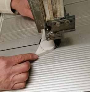
The Well.
This was to be a larger decorative ring resting in the upper surface of the
base.
Again, Paul had prepared a circular piece of his material attached centrally to
a MDF faceplate with double sided sticky tape.
The outer edge was fashioned with an undercut
using a scraper as before.
The scraper was then worked from the highest point towards the centre following
the curve already made.
As seen in the intended profile above, the outer curved edge finishes at the
bottom of the material while the inner curved edge finishes higher up.
The desired shaped ring was cut with a parting tool straight into face of the
circular prepared piece.
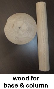
The Base
For the demonstration, Paul had prepared the base by mounting between centres;
turned a cylinder of appropriate diameter; shaped an upper surface.
A hole had been drilled in from the side to the centre running close to the
underside and another hole drilled down the centre to accommodate an electric
cable to enter the base at the side and bend upwards and eventually through the stem to a light
socket.
The top of the base was mounted in a Screw Chuck.
The outer edge of the underside was squared off and the centre slightly
hollowed. A ridge was turned within this hollow at an appropriate diameter for
Paul's jaws to grip the base in expansion for the next step.
Having turned the base around, the top of the base was pared off sufficiently to
allow the first turned Knop described above to sit in perfect proportion to its
diameter. Then the same drill used to cut the hole in the Corian Knops was
placed in a keyed chuck & arbor fitted to the tailstock and used to bore a hole
sufficient to receive the spigot soon to be turned on the stem.
Next, the internal diameter of the shaped Corian
ring (that was to form the Well) was measured and marked on the base.
A Parting Tool was used to carefully get the width exact for the ring to fit
snugly.
Once the ring's inner edge was right, the Parting Tool was used to deepen the
cut a little at a time until the ring's outer edge became flush with the base.
The Stem
Having turned the stem between centres to a cylinder of a size to allow for some
shaping by the finish, Paul changed the tail stock centre from a pointed tip to
a hollow ring type, which allows for a Shell Auger to be used through the tail
stock for boring a long hole up the centre for the electric cable.
With the stem re-mounted between these centres, Paul placed the point of the
Auger at about half way along the outside of the piece and marked the Auger with
a piece of sticky tape adjacent to the back end of the tail stock.
He started the lathe and fed the Auger through the back of the tail stock until
it eventually started to bore into the stem.
It now required a gentle steady feed with frequent withdrawals to clear the
waste sawdust in order to prevent the Auger going off centre. Once
deflected, you would never be able to correct it back on course.
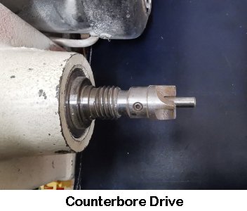
Once the tape mark on the Auger reaches the back of the tail stock, Paul
stopped, changed the 4-prong drive centre for a Counterbore Drive, reversed and
remounted the piece for boring the rest with the Auger. Paul advised that
he could feel the Auger in his hand go soft just as it broke through the first
hole.
The hollow ring tail centre was replaced with the pointed tip centre and the
stem returned to between centres with the tail stock supporting the end destined
for the Lamp's base.
After setting his Spring Calipers to the size of the drilled hole in the base,
Paul used a Parting Tool to turn a spigot of appropriate length & diameter to
fit the base, remembering to account for the depth of the first Corian-like
embellishment he had turned.
He then continued to finish shaping the stem and added a shoulder plus another
Corian-like knop to go beneath the light bulb socket.
Paul had a brass insert that screwed
directly into the drilled hole of the stem. This insert couples the bulb socket
to the stem.
Top Tip
: If a
Lamp is going to be sold at some point there are some electrical goods
regulations that must be followed eg. cable clamp.
To avoid this problem, the simplest way is to sell it un-wired with the customer
arranging for a competent electrician to do so.
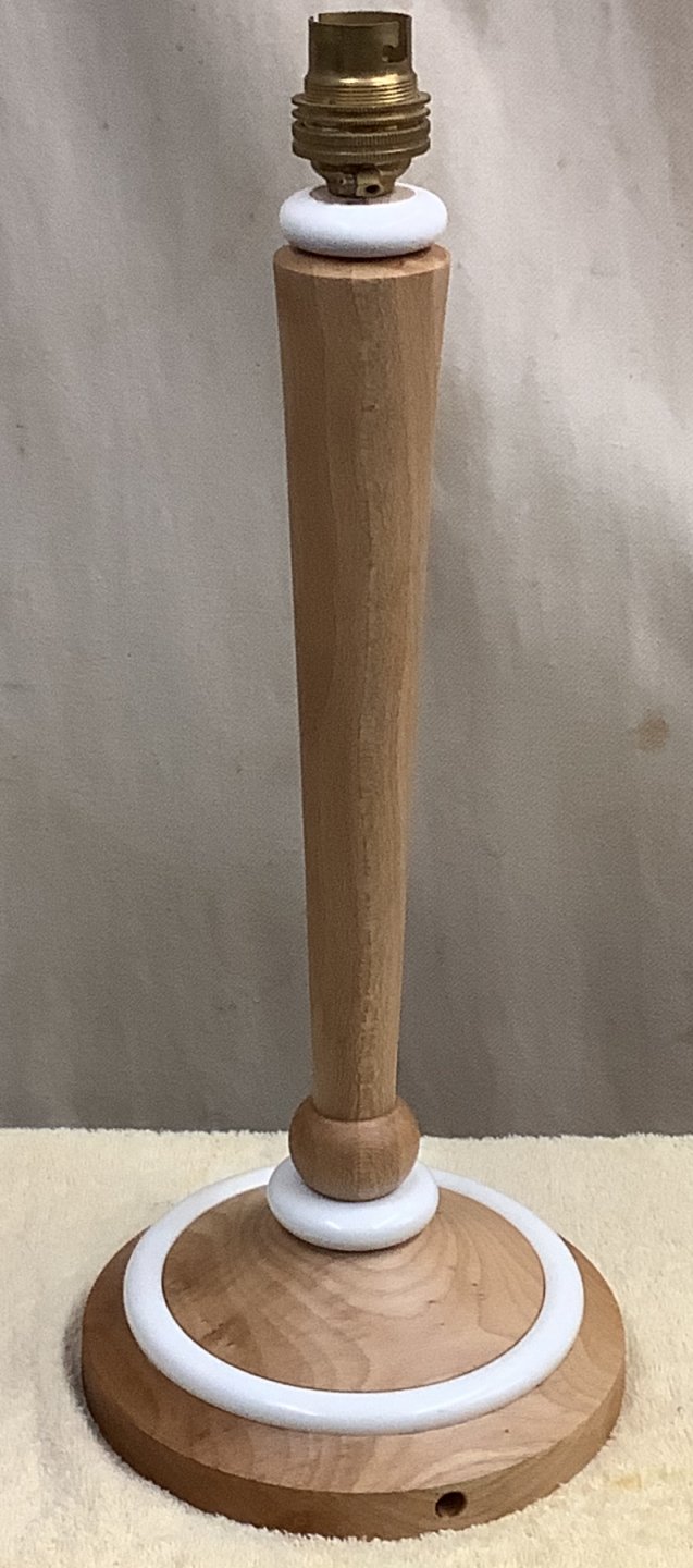
And finally, below all the parts individually
and assembled with a coat of oil applied.
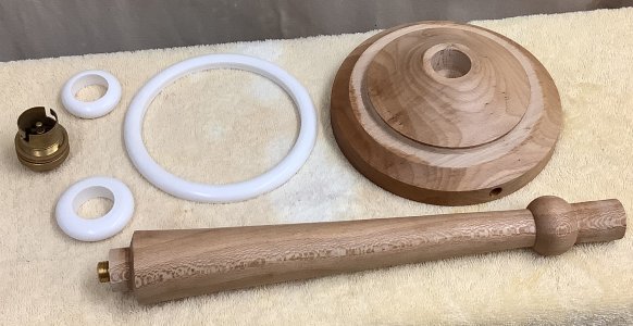

(click for close up view)
The February Competition was set for a two-part Table Lamp or Candlestick (base
and stem)
with "added value" eg colour, texture, other materials etc.
<Competition Results>
<to
index>
December 2021 -
DEMO
4
Box of Contrasting Woods
with Paul Reeves
Thursday, 16th December 2021 at MWCC Club Night
The wood types best suited for box making have
moderately tight and even grain which won't present too many turning problems.
The tops & bottoms of boxes are better designed to be end grain; even so, softwood options will invariably tear out whereas
hard woods tend to cut cleanly.
Popular choices are from the Rosewood and Fruit wood families. Woods to avoid
have well spaced and well defined growth rings with fluffy open structured wood.
Likewise, some spalted woods should be avoided if the paler parts are
significantly softer than the rest.
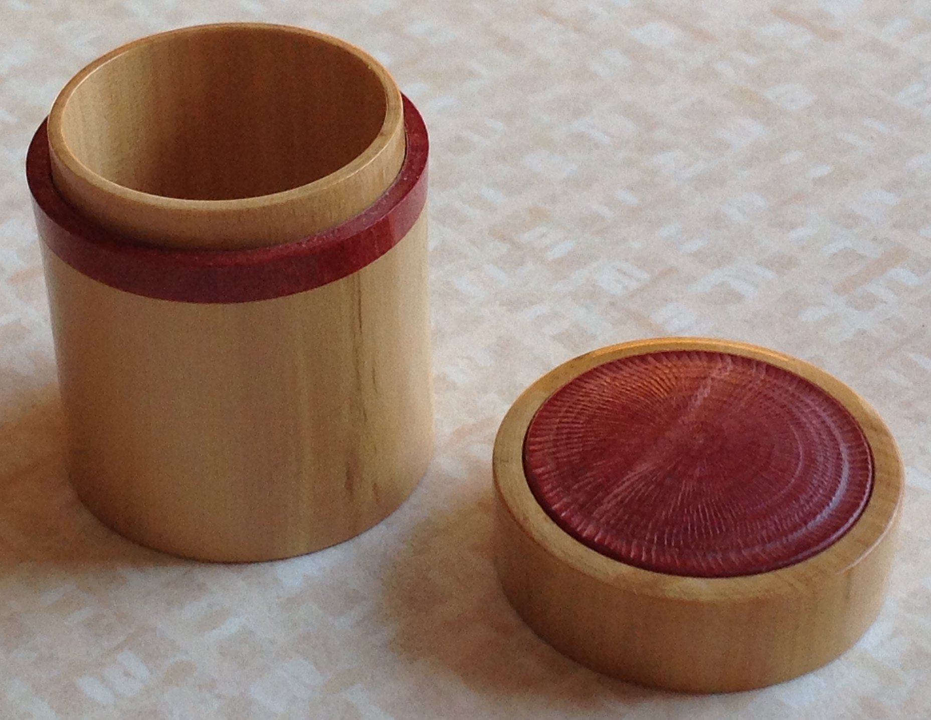
Paul chose to turn a small box made from Box Wood adorned with the contrasting colour
of Pink Ivory to give a seasonal effect.
Box is an ideal wood for very thin walls and finishes beautifully with Carnauba
Wax applied.
Pink Ivory can provide a natural shine even from a tool finish.
For the sake of saving time during the
demonstration, Paul had prepared the Box blank between centres, turned the piece
into a cylinder of desired diameter with a spigot suitable for his chuck at
each end.
He had then parted the lid from the base at approximately
⅓ : ⅔ ratio.
[ Top Tip
: Before dividing your original piece into box
lid & box base, draw a pencil line along the cylindrical side so that once
separated, any blemishes in the wood can be quickly lined up].
Cabochon
(a smooth domed ornament; polished but unfaceted)
With the Pink Ivory secured in the jaws of his chuck, Paul used a broad parting
tool to turn a cylinder to a suitable diameter and depth to fit within the top
of the prepared lid.
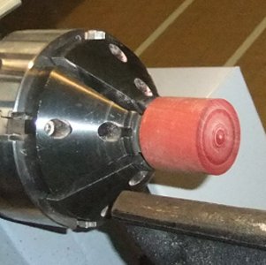
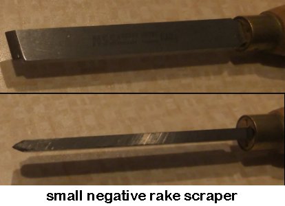
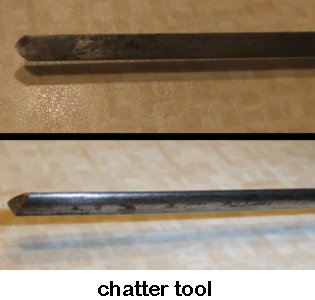
A dome was formed on the front with a small negative rake scraper. Ordinarily, if done carefully (ie
with no scratches) there would be no need to sand. However, as Paul was going to
decorate using a chatter tool, the piece needed to start from a very shiny
finish for it to show up later between the chatter marks. He achieved this with
400 grit.
A chatter tool should only be used on end grain because applying to side grain
would result in marks of differing depths as the piece turned between the two
contrasting densities of along & across grains.
The chatter tool works because its end is sharp and flexible. Its effectiveness
is improved by slowing the lathe speed down a bit and presenting the tool tip
pointed slightly down.
When satisfied with the resulting design, the disc was parted off to the desired
depth and any pimple removed.
[ Top Tip
: If the box base is going to be hollowed out
with a Forstner bit, the above process can be repeated and adapted to produce a
matching thin disc for the inside bottom of the box to hide the centre dimple made by the Forstner ].
Decorative ring to go around spigot of box base.
Using hardwoods makes it easy to get a precise fit.
With the Pink Ivory still in the chuck, Paul used his parting tool to turn a
cylinder slightly larger than the diameter of the box base - this will allow a
clean precise cut-to-size later in the process when the base and lid are taped
together.
Having calculated a suitable diameter for the spigot, he carefully transferred a mark to the front of the Ivory using dividers.
The centre recess was
removed to a few millimetres deeper than the planned depth of this decorative
ring.
This could be started with a gouge or a Forstner drill bit in a Jacob's chuck or
(as Paul chose) with an old drill bit in a handle held against the centre of the
front as the lathe was turning. Whichever way was selected, the final cut to
the inside edge was completed with a Box Cutter to the mark made by the dividers earlier.
Paul parted off the ring and cleaned up the surfaces (that would be glued to the
base) carefully with fine abrasives for a close fit.
Spigot on base
for decorative ring.
With the box base mounted using the prepared tenon, Paul squared off the front.
Having measured the inside of the decorative ring carefully with callipers, he marked
the same diameter on the front using dividers. The length of the required spigot
was calculated to incorporate the width of the ring and then sufficient to grip
the sides of the lid but avoiding making the lid's top too thin. Using his broad
parting tool again, he made a cut at the calculated length and formed a parallel
spigot to just short of the earlier dividers mark. The final fit was done
gradually with the negative rake scraper with regular cross checks against the
decorative ring. Paul finally glued the ring to the base using some superglue.
Inside of lid to fit spigot.
With the box lid now mounted on its
tenon, the spigot was measured with callipers and the underside of the lid
marked as described above.
To make this small recess, Paul initially used a spindle gouge from just inside
the dividers mark towards the centre and then from in to out towards the mark.
The box cutter was used for fine adjustments of both depth and inside diameter
with regular fitting cross checks with the spigot on the box base to avoid a
loose fit. [ Top Tip
: don't be tempted to use
abrasives at this stage because different densities around the piece will abrade
away differently and the recess would become oval. It would also be difficult to
maintain a square fit. A box cutter avoids both these problems ].
The correct fit was when there was a slight resistance to removing the lid.
Cabochon fitting.
Paul had removed the box lid from the
chuck, lined up the lid to the base using the pencil mark drawn down the side of
the cylinder at the start and closed the box. Some insulating tape (or similar)
was applied around and over the joint of the base & lid before mounting the base
spigot into the chuck. The lid's tenon was turned away and the process of making
a small recess for the cabochon was exactly as the previous paragraph - other
than the fit was finished by gluing the decoration into place.
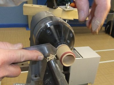
Next, Paul used his spindle gouge to trim the insulating tape off, the
decorative ring back to the outside of the box and matched the lid to the base
to a smooth finished shape. Finally, Paul used a thin parting tool to mark
a groove where the bottom of the box would eventually be parted off. This
allowed him to calculate the maximum depth he could take from the inside of the
base.
Hollowing out base.
With the lid removed and the lathe started up, Paul used the tip of a skew to
mark the centre of the spigot. He now calculated how deep he wanted to go
inside the base measured from the top of the spigot and allowing for just how
thin he wanted the base of the box to be.
He took his old drill with its handle that he used above and marked this depth
with the aid of a piece of tape around the drill so that when its bottom edge
was flush with the top of the spigot, he would be at the correct depth.
With the lathe at a moderate speed, the tail stock well out of the way and his
old drill in his hands, Paul gently presented the drill tip to the centre mark
keeping it as level and square as he could tell before pushing the drill into
the wood. As it went deeper, the rotation naturally guided the drill to run
absolutely true. Paul only allowed the drill to go as deep as the leading edge
of the tape before withdrawing.
This hole made it easier for a gouge to remove the centre. Also, by keeping
close attention to the bottom of the box, he was able to see when he was nearing
the bottom of the drill hole and hence his selected depth.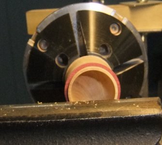
The next decision was whether the shape of the base inside be curved (use a
round scraper) or square (use the box cutter). His audience opted for round.
Whichever is used, it is vital that the scraper/cutter must move horizontally in
and out.
Any slight deviation from level will result in the cutting edge digging deeper
into the wall of the piece as the tip travels further away from its pivot point
on the tool rest. The same problem arises if the tip moves away from being
parallel to the 'ways' (the rail-like metal bars that the tail stock slides on).
One aspect to remember when hollowing is that the walls will become heated by
the friction of the cutting tool. This results in driving moisture out of
the walls (the thinner the walls, the more the effect) and the diameter of the
box will shrink slightly. Suddenly your previously perfect fitting
lid has become very loose! Don't panic. Leave the piece alone
and after some 12-24 hours, the wood in the walls will have cooled, had time to
re-absorb the lost moisture from the natural humidity in the air and come back
to that perfect fit.
[ Top Tip
: don't try to turn
the inside of a lid to fit a spigot immediately after you have hollowed out the
base. You will probably end up with the lid welded tight onto the spigot ].
The tool finish on the Box Wood was good enough to proceed with parting off.
The thin parting tool was used in the earlier made groove and parted off the box
base from its tenon. If it had been necessary, the box bottom would have been
finished off by reverse chucking.
Paul changed his chuck for buffing mops, which he
used to smooth the surfaces with just the White Diamond compound. He feels that
the Tripoli compound with its red colour tends to darken the finish of the pale
Box Wood. Following a change of mops, he finished the buffing with Carnauba wax.
Don't put too much wax on the mop wheel as this can lead to a hard ring building
up, which will need wire wool to remove.
The technique for all the stages is a steady gently stroke of the piece
against the mop wheel and keep slowly turning it in your hands.
[ Top Tip
: spreading a folded towel or similar on the 'ways' underneath the mop wheel
helps to avoid dents if the spinning mop should rip the piece out of your hands ]
Pushing the piece hard onto or holding it still against the mop wheel will
result in a build up of heat which could distort the piece or burnish a flat
into the side.
Be warned - buffing a thin close grained wood to a magnificent sheen does make
the piece appear just like plastic.
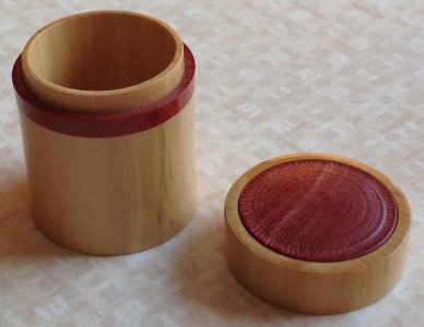
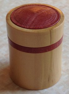
(click either for close up view)
The January Competition was set for a box comprising of
2 or more contrasting woods.
<Competition Results>
Below are some more examples of Paul's boxes with
contrasting woods for inspiration :-
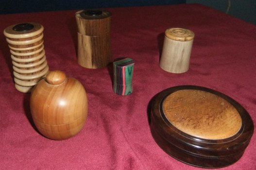
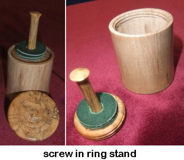
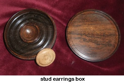
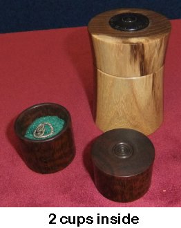
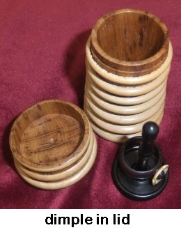
The 'screw in ring stand' has a ring caddy
which slides up & down when inside the box but held steady by a screw thread
just below the brim.
The 'stud earrings box' has small holes for the stud pins and a central
container for the selection of ornaments to go on the studs.
The '2 cups inside' has one ring box with another lidded box on top, both having
a soft-close fit inside the outer box.
The 'dimple in lid' has a ring caddy that is the precise height to hold the top
of the caddy in place when the lid is on, which stops it rattling about.
(photos by
Rick Patrick & Paul Reeves)
<to
index>
November 2021 -
DEMO 3
Offset Turned Bowls
with Paul Reeves
Thursday, 18th November 2021 at MWCC Club Night
When is a bowl considered offset?
Take the three examples below.
The first has its bowl centre only slightly away from the centre of the rim of
the piece.
The second has its bowl positioned to avoid the natural voids and imperfections
(further enhanced with some piercing). [ Top Tip
: if you wish to pierce Yew, plan to do so with 'green' wood as Yew gets
very hard when old]
The last has a markedly offset bowl from the centre of the piece which has the
advantage of providing a large part of the rim available to decorate.
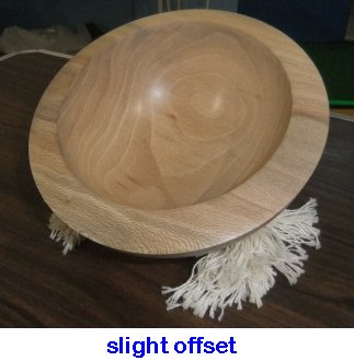
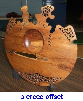
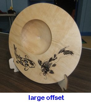
Note that with any offset, the piece will have a tendency to tip towards the
thicker denser edge and take up a natural 'show me' stance.
The slight offset example takes up this position but Paul has helped to maintain
it with a seat of soft rope with the strands at each end pulled apart to
stabilize the orientation (which he prefers rather than standing the piece on a
separate circular stand). The other two examples have thin rims and are
best displayed using plate stands.
Another important consideration is that when the
piece is centred on the offset, it will always be out of balance.
The more the offset (or wood removed in the pierced case) the greater the
imbalance.
Consequently, it is important to ensure the lathe speed is minimal BEFORE
starting to turn your piece in the offset position. Many lathes can only
change their speed with the drive rotating and it will be a bit late to realise
it is too fast when your lathe is shaking itself across the floor!
Although there are several Eccentric Chucks
especially designed for offset turning, there is no need for such complicated
chucks because a combination of a standard chuck with a Cup Chuck or a Screw
Chuck can achieve the same results.
For best results, choose a blank with a
decorative feature; eg burr, rippled, exotic or unusual wood. It could be
first mounted either on a Faceplate or a Screw Chuck. Paul had chosen a spalted Ash bowl blank, which
he mounted with its pre-drilled centre onto a Screw Chuck.
[Top Tip : if your Screw Chuck
extends from a flat plate, bevel the pre-drilled hole in the base; this prevents
any scurf (from the Screw Chuck as it bites into the piece) protruding and
preventing the piece from being held flat against the chuck's plate]
Ensure that your pilot hole is just the length of the Screw so that it will
later disappear when gouging out what will become the inside of the bowl.
As with last month's 'Turning a Plate' demo, you could use just 1 tool to make
this project; eg a 1/2" spindle gouge or a small bowl
gouge. Turn the the back to a curve of your choice; eg hemispherical,
conical, parabolic shape. Sand to a final finish (see Principles' below)
then seal with Sanding Sealer, wiping off any excess. Pay particularly attention
to sealing the end grain in order to prevent hot glue from penetrating deeply
down the grain in the next step.
Sanding Principles
Wisdom has it that the secret to good sanding is to avoid leaving tool marks
in the first place. It's probably best to leave that wisdom with the
Professionals who turn day in day out, and an aspiration for us especially
considering the Club sells more than £400 worth of abrasives per year.
The procedure for we mortals is :
1. The first abrasive is used to smooth away dents and scratches.
But after doing this, they will leave behind smaller scratches from the abrasive
particles on that paper just used.
These small scratches are then removed by using an abrasive paper with smaller
particles, which of course will leave behind even finer scratches ... and so on
until you no longer see or feel any scratches (although a microscope would see
them!).
2. Before using abrasives with the lathe turning, remove or move well out
of the way all tool rests (and tail stock, if not in use) to avoid your hand
being injured if it slips off your work.
Reduce lathe to a low speed before applying the abrasive (to prevent overheating
the wood) and keep the abrasive moving (to reduce ring scratches on the piece).
Set up adequate extraction to reduce dust from filling up your workshop and your
lungs! Certain trees & plants create toxic dust; eg Yew, Rosewoods, Oleander and
indeed most woods to a varying degree. Probably best to use a mask as well as an
extractor.
3. Start at the low number grits. (The grit number refers to how many
particles could be squeezed into a standard area). P120 will probably deal with
tool marks but holes (eg from end grain pull out) might need a lower grit number
just on and around the flaw.
Using a backing pad can help in giving a more even sanding. Keep a steady
pressure on your abrasive/pad but avoid pressing heavily.
4. Stop the lathe and check if the worst scratches are gone. If some are
still there, try rubbing by hand with the lathe motor off using the same grit
ALONG the grain until improved.
5. Brush/blow off the dust to avoid the next grit picking up sharp dust
particles and putting more scratches in than they smooth out.
6. Select the next finer grit (typically 80
→ 120 → 180 →
240 → 320 → 400 → 600 → 800) and proceed as described in para 3 above. Note :
for most jobs, you won't need to progress through all the grits above. Just stop
when you see and feel a smooth surface. For all spalted woods and wide grained
woods like Ash, you will need to restrict sanding to just the low number grits
because the parts between the spalts or annual rings are so much softer that
they will wear more under the abrasive and you will end up putting ridges into
your piece. Dense woods can become exceedingly smooth and polished if you work
down to P400 and finer.
7. If your lathe can, then change the direction of spin between different
grits to avoid one area repeatedly getting affected more than the rest; eg a
bowl with long grain and end grain - the end grains have more resistance than
the long grains resulting in the end grain being sanded away differently at its
leading edge. However, changing direction lessens this outcome.
Paul chose to create a Cup Chuck connected to the
driven chuck via a Faceplate. The advantage being that with the outside
already completed, he only had to finish the piece mounted while glued to the
Cup Chuck without the chore of reverse chucking to remove a spigot.
The Cup Chuck was made from waste wood or an old bowl blank of about 6" by 2".
A faceplate to fit the chuck was screwed on centrally and mounted in the
standard chuck. The screws had to be reasonably short to avoid any chance
of their ends breaking through the depression being gouged from the other side.
Consequently, he made use of all 6 screw holes. The depression was planned
to match the curve of the piece and as deep as possible
without the Faceplate screws penetrating the bottom, even after the Faceplate
was later offset.
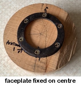

Once satisfied with the fit and remembering to try and avoid the two end grains,
Paul started to hot glue by holding the piece to the chuck (gauging carefully by
eye that the flat surface was sitting perpendicular to the axis both up & down
and side to side). He dropped the glue onto the Cup Chuck so that it
flowed down into the V-shape and made contact with the piece over about an inch.
Patiently allowing a couple of minutes for the glue to set, he rotated the whole assembly
about 60° and repeated another five times.
[ Top Tip
: Use polythene glue sticks rather than
other general purpose sticks because after polythene glue cools, it can easily
be removed by warming with a hot hair dryer and being 'thumb rolled' off
]
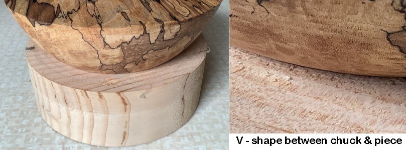
Once all the glue had hardened, the face was flattened off with a
gouge. [Top Tip : It is easier to achieve
an accurate flat surface by keeping your elbows to your side and rock your whole
body forward rather than attempting with out-stretched arms.]
The level face was sanded and sealed as above.
Then the LATHE SPEED WAS REDUCED to minimum because the next step was to offset.
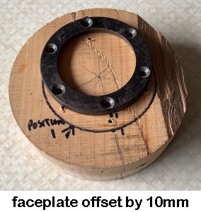
The entire Faceplate, Cup Chuck and piece was removed as one
section.
The Faceplate was unscrewed, repositioned 10mm offset and re-screwed.
Paul recommended that a 15mm offset be considered the maximum because 15mm would
result in the bowl rim max and min differing by 30mm and any larger could
restrict your options of the eventual diameter of the bowl.
With the piece now offset, it will be unbalanced and would
benefit from counterbalancing.
Paul had a size variety of lead flashing pieces to choose from.
The side of the Cup Chuck that was nearest to the lathe's spindle centre (to
compensate for the wood that was there on the opposite side) was where he used
two screws to secure the lead.
In his experience of harmonic vibrations, Paul reports that one can expect to
gently increase speed through the first vibration which will eventually settle
down, but as one slowly increases speed towards the start of a second vibration,
immediately back off the lathe speed a little.
The faster the pieces turns, the cleaner the cut so finding the right lead
weight to reduce vibration and increase turning speed, the better.
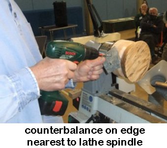
Paul turned out the inside of the bowl using a prepared card
shaped to the desired profile to guide where and how much to remove.
Further decoration was considered. With a flat surface with an offset hole, a
plain wood might be worth accenting with a defining point, eg a small cove at
the bowl rim. This might not suit for some figured or spalted wood.
The consensus of those present opted for no further decoration as the spalted
Ash was decoration enough.
The piece was sanded as before. After thorough brushing out, it was sealed
again.
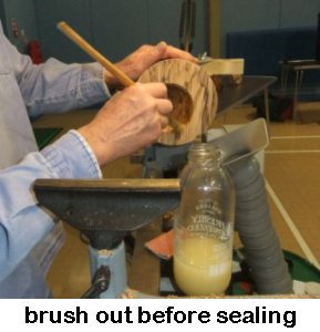
A hair dryer was used to gently warm the glue so that it could be
carefully removed to free the piece from the Cup Chuck. Note : It's
important not to overheat woods (eg. like Yew, Cherry, Macrocarpa) or else there
is a danger of causing surface crazing.
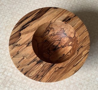
(click for close up view)
The December Competition was set for a
turned example of an offset bowl.
<Competition Results>
(photos by
Graham
Turner, Rick Patrick & Paul Reeves)
<to
index>
October 2021 -
DEMO 2
Turning Plates & Platters
with Paul Reeves
Thursday, 21st October 2021 at MWCC Club Night
What's the difference between a plate, a platter and a shallow bowl?
In Paul's humble opinion, you need to apply the
TIP RULE.
If you press down within the inset of the piece about ¾ out from the centre and it doesn't tip - it's a
plate/platter.
If it does tip, it must be a shallow bowl.
One certainly doesn't want to find a load of food in one's lap.
When does a plate become a platter? When it's big enough!
A single platter is normally used to cater several plates.
Plates tend to be functional while platters tend to be impressive.
If making a utility plate/platter then choose a plain wood to avoid food getting trapped
in any decoration.
Paul prefers to decorate the rims of platters to achieve the spectacular.
It can also help to select a blank that has some marked feature (eg figure,
spalted, burr)
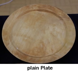
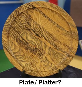
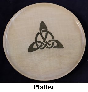
Turning a Plate
There are 2 obvious ways of mounting : screw a faceplate ring onto the front
face - OR - hot glue an MDF backplate which can then be driven via a chuck with a
screw fitting or connected to a ring plate.
The first option is only suitable for thicker blanks as it needs to be fitted
with short screws to attach into the central waste wood and will also require an
expanded dovetail in the back to finish turning the front.
The second has the advantage of extra room to turn the back edge of the platter.
You could use just 1 tool to make this, eg a 3/8" spindle gouge or a small bowl
gouge.
Paul started with pull cuts - with just the small radius touching - to level off
the front surface for a couple of inches from the edge.
The edge was rounded off and the back was shaped by pull cuts (or a bevel cut if
using a thick enough MDF backplate)
If your lathe allows, try swivelling the headstock away from the turner to get
easier access to the back.
The work was then returned to finish off levelling the front surface.
It will help if you gradually slow your movement of the gouge as it gets closer
to the centre; this will result in the feed speed of the wood being similar to
the cuts nearer the outer edge.
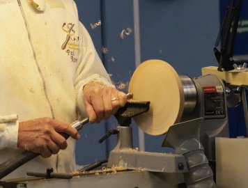
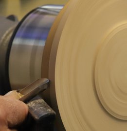
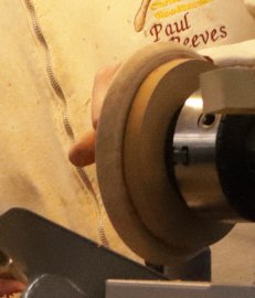
When taking out the central waste wood, it's a good idea to purposely leave a
pimple in the centre. If this is done from the first indent cut, it will give a
precise indication of how deep your last pass went and help avoid the platter
bottom getting too thin.
Check for levelness with a ruler (if there is room) or else with a short block of
wood you are confident is flat.
Shave off the pimple just before the final cut.
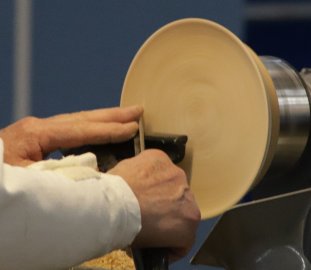
With the lathe at rest, start sanding along the grain using a fresh/new piece of abrasive
supported with a block to flatten out the inevitable
irregularities. Then, with the lathe speed much reduced (to avoid excess heat
and clogging the abrasive), sand while keeping the block moving. Should the
abrasive ever be held still with the lathe turning, it is inevitable for scratch
circles to appear in the piece.
Work through the grits (changing turn direction if available) and after every
other grit, switch the lathe off and finish by hand along the grain.
To finish the back, remove the Ring/MDF and reverse the piece into cole jaws or
whatever your preferred method of reverse turning.
If you used hot glue, be careful with any remaining traces as it can be quite
'grabby'.
A gentle pull cut normally clears the surface well.
If no foot is planned, level off remembering to slow the gouge head movement
nearing the centre.
Cross check with a ruler although a marginal central dip would be acceptable.
If a foot is planned then proceed as you did with the front indentation.
Use abrasives as described above.
Turning a
Platter
Using a test piece of Ash (his chosen wood for this piece), Paul had compared
two ways of ebonising in readiness for decorating; that is by 'burning' or by
spraying 'lacquer'. Paul found that burning resulted in the Ash bleeding some of the
surface black down into the wood resulting in a muddy finish when he cut through
to the underneath. However, the sprayed surface showed a sharp contrast when
cut, particularly with his pale Ash.
The platter's rim was shaped and sanded much as for the plate above.
The outer edge was ebonized with the spray while the centre wood was still in
place, in order to prevent overspray getting onto a finished surface.
The chosen pattern was applied using a Proxxon V-shaped carving gouge to create
grooves - this method is a lot quicker and produces a smoother finish rather than trying to
manually cut grooves with a mallet and chisel.
The round flower centres were produced with a ball carbide cutter in a Dremel.
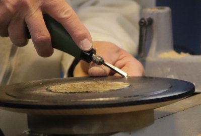
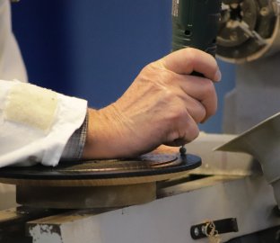
The leaves and flowers were painted on with a small flat brush.
Paul used Jo Sonja's iridescent paints (other producers : Chestnut, Arteza,
Pebeo) which become vivid colours when against a dark background.
But be warned, when squeezed out onto a pale surface, all the colours will look
unbelievably identical creamy splodges. So do make sure you remember/label each
splodge with its actual colour. Also, very little is needed to cover a lot. On
the night, Paul found he had wasted more than he had used.
Finally, the solid colour of the flower centre was a yellow acrylic.
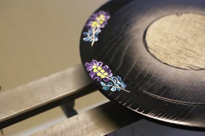
It took at least 20 minutes for all the paints to dry sufficiently for a coat of
clear acrylic gloss lacquer to be applied to seal and protect the decoration.
After being left to dry overnight, the platter's waste wood and back was turned
and finished as described above for the plate.
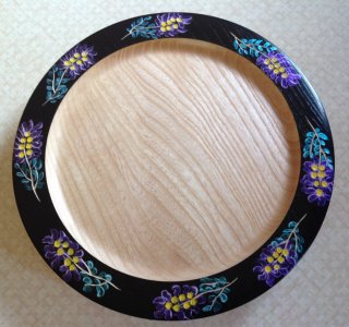

(click for close up view)
The October Competition was set for a
turned example of a plate or platter.
<Competition Results>
(
photos by
Mark Codling & Paul Reeves)
<to
index>
SEPTEMBER
2021
-
DEMO
1
Treen Hand-Held Mirror
with
Paul Reeves
Thursday, 16th September 2021 at MWCC Club Night
Treen is a generic name for
small - handmade -
functional - household object - made of wood.
Treen is the 'Old English' word for "of the tree" and used by all until 'mass
production' brought about lower prices and gradually, modern wood alternatives.
Old treen tends to be obvious from a look underneath the piece. To earn a
living, the carver/turner had to work so quickly that very little of what's not
seen ever got touched. Speed of production usually meant the worker didn't need
many gouges. Nowadays, production is invariably for the pleasure of working wood
and the creative satisfaction of making something useful.
'Treenware' covers a multitude of sins. Toys, tools, moulds, practical or
humorous gadgets etc; but treen is distinct from furniture making.
Below are a few examples :
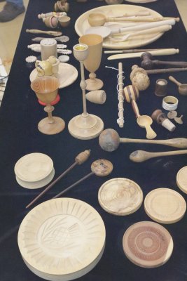
For the demonstration, Paul elected to turn a
4" Hand-Held Mirror out of Yew in two parts; ie the mirror surround being face
plate turned and the handle being spindle turned.
As the mirror surround was to be
decorative on both faces, Paul wanted to avoid any chuck recesses. An
approximately 6" diameter by ¾" thick round
of Yew with an attractive grain was prepared with a hole in the edge to receive
the handle spindle (this procedure needed care to get the hole drilled precisely
lined up centrally). It was then carpet taped to a base plate to fit the chuck.
A parting tool was used to mark the exact width of the mirror before taking out
the centre leaving a flat surface for where the edge of the mirror could be
glued. The rest of the centre was carefully removed to over half depth (to
reduce the final weight) but would still allow the back face to be about 4 or
5mm thick when finished.
Paul commented that using small tools for this job was a good way to improve
one's gouge technique as lots of small cuts are needed.
The outer edge of the surround was shaped keeping in mind the need to copy that
same shape from the other face.
Paul highlighted that when using abrasives or buffing Yew pieces, they are prone
to getting too hot very quickly, which would lead to cracking or splitting. This
is avoided by reducing downward pressure; regularly clearing the dust off your
abrasive (eg with a small piece of carpet); dusting off between grits using a
brush or tack cloth.
The face was then treated with sander sealer prior to decorating with a
texturing tool and wax filler. (Various texturing techniques are to be found
in the Archive
<HERE>)
Paul had decided to use his Decorating Elf with a
Ball Cutter and gold paste wax/gilt cream to in-fill.
The Elf was used to apply crisp surface cuts to reach beneath the sander sealer.
The patterns were subsequently framed within outline indents and a
burnishing/bronze wired brush applied to remove the fibres thrown up by the
cutter.
A generous coat of embellishing paste was applied evenly over the textured areas
and allowed to dry a bit before the excess was removed. Paul first used a
paper wipe moistened with white spirits to loosen the paste before using a clean
paper wipe across the line of indents. If this had been wiped along the
indents, it would likely remove most of the paste.
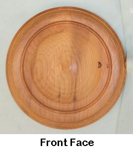
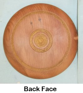
(click 'Front Face' for close up view)
The surround was removed from its base plate and the
current depth in the middle was measured to plan how many millimetres the back
face needed to have removed to leave a 4 to 5mm wall thickness. The piece now
needed to be mounted for the back face to be completed. The simplest
method would have been to use a chuck to expand against the mirror rim, but the
available chuck was not large enough so the base plate was adapted as a Jam
Chuck by turning out a spigot that just fitted the mirror rim and secured with a
few daubs of hot glue.
Once the glue had hardened, the back face was turned
away to the calculated wall thickness followed by the outer edge made to match
its opposite side. Abrasives were used along the grain with the same
precautions of dealing with Yew wood as above. Sander sealer applied and the
piece decorated in sympathy with the front face.
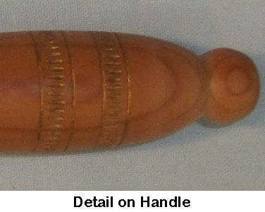
An appropriately sized spindle handle was fashioned & decorated as above before
gluing into the hole originally prepared in the mirror surround.
(click for close up view)

(photos by
Mark Codling, Rick Patrick & Paul Reeves)
The September Competition was set for a
turned example of piece(s) of treen.
<Competition Results>
<to
index>
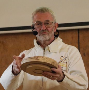
January
2020
- Demo 5
Spindle & Face Plate Turned
with
Paul Reeves
Thursday, 16th January 2020 at MWCC Club Night
Three Legged Stool
This Competition is to create a piece which
combines spindle driven work with face plate / chuck driven work.
This invariably results in two (or more) pieces of wood turned separately and
finish up joined together.
Effectively, some will be turned along the grain, the rest will be turned across
the grain.
This makes for a very broad range of
designs.
Below are a few examples :
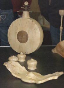
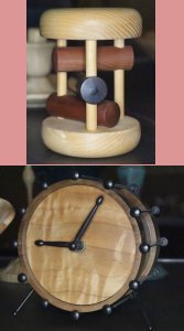
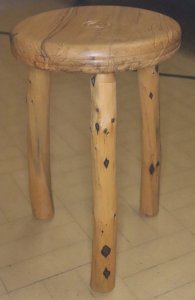
For the demonstration, Paul elected to turn a
three-legged stool out of well-dried spalted Beech; ie the legs being spindle turned and the seat being face
plate turned.
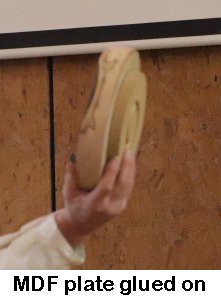 A
roughly rounded seat had been band sawed from a plank and 5 blobs of hot glue
were used to attach a MDF face plate to the intended seat top. The MDF had been
prepared with a shaped hole to fit chuck jaws under expansion which allowed the
roughed-out seat edge to be rounded out, the under-seat squared off and mortise
centres carefully drawn at 120° to each other about 2" in from the edge. (If
these were inaccurate, when the mortises were being drilled at about 12½° inward
incline, the seat would not have been level). The underside was also hollowed
out to fit expanding jaws for turning the upper surface but leaving enough
centre wood to support a tailstock for finishing the underside.
A
roughly rounded seat had been band sawed from a plank and 5 blobs of hot glue
were used to attach a MDF face plate to the intended seat top. The MDF had been
prepared with a shaped hole to fit chuck jaws under expansion which allowed the
roughed-out seat edge to be rounded out, the under-seat squared off and mortise
centres carefully drawn at 120° to each other about 2" in from the edge. (If
these were inaccurate, when the mortises were being drilled at about 12½° inward
incline, the seat would not have been level). The underside was also hollowed
out to fit expanding jaws for turning the upper surface but leaving enough
centre wood to support a tailstock for finishing the underside.
Paul explained that he liked stool leg tenons to
go about an inch into their mortise; but without some trickery, this would make
the seat look very heavy. The deception is achieved by bevelling/coving the
under-edge to leave enough thickness for the leg sockets. Weight can be further
reduced by hollowing out underneath between the legs.
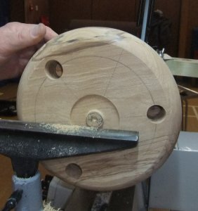
After the underside had been sanded
with the lathe on, followed by sanding along the grain with the lathe off
through the various grits, the MDF plate was prized off and the worst of the hot
glue removed by hand before being remounted in the chuck to work on the seat
upper surface.
If using a gouge to remove the last of the glue, be aware that a push cut can
result in a 'dig in' as the glue residue might snag the tool tip. A better
method would be to use a pull shear cut.
Now a decision has to be made; are
we making a side table (needing a flat top) or a stool (with a slight dimple to
improve comfort)?
This was to be a stool so a gouge rounded off the top outer edge to prevent a
sharp edge under the sitter's thigh; and a gentle indent was turned.
The top was finished by sanding through the various grits, stopping to sand
along the grain, inspecting, brushing all dust off before reversing the lathe
direction with the next grit.
The piece now had to be remounted in
either cole jaws or else between a tailstock and a grip pad up against an MDF
face plate. This allowed removing the chuck jaw bevels and to finish hollowing out
the centre of the underside.
Care must be taken with regard to how deep to hollow out. Beech does not turn
well when thin!
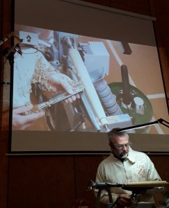
It was now time for spindle turning.
With 3 identical legs to produce, it is helpful to make a 'story stick'
using a piece of wood with nails (or holes for an awl to poke through) to
delineate the overall length and where significant highs or lows will be on the
finished piece. Paul favours a small rectangular stick with appropriate
drilled holes for an awl to make an accurate mark when placed upon the tool rest
while against the mounted wood.
His design for these legs was a baseball bat shape
with a hemispherical foot and a simple straight taper into the tenon, without
leaving a shoulder (which would be difficult to
achieve without appearing unsightly at the inclined joint between leg and seat).
Tonight's legs just needed a Story Stick with a bottom end where the foot starts, a start point for
the half round foot, a start point for the tenon and an end point of the tenon.
Having marked his spindle, Paul explained he found that a slightly oversized spigot is better formed at the tailstock end
using a parting tool. He then angled his long tool rest to parallel the
hemisphere start and the tenon start marks as a useful guide for the required
taper to fade into the tenon. When trimming down the taper with the tool
rest at an equal distance, remember the need to gradually lift the gouge handle
as the leg's diameter gets smaller.
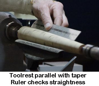
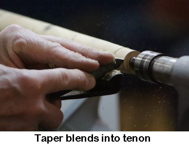
In order to leave room for glue, Paul finished off
the tenon to a loose fit with a chamfer to aid assembly.
Traditionally, a bus ticket was used to take up the slack on an old stool where
the legs had shrunk with age or use, for example, in the milk parlour!
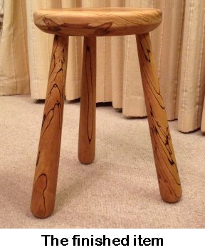
(photos by
Mark Codling, Ian Wright & Paul Reeves)
The January Competition was set for a
turned piece(s) comprising of a combination of cross-grain with
along-grain turning in each completed piece.
<Competition Results>
<to
index>
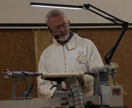
Paul Reeves
Demonstration of Off-Centre Turning
Thu, 20th February 2020 at MWCC Club Night
Eccentric turning can produce elegant and aesthetically
pleasing pieces, for example :-
Polygon Shaped Spindles
Twisted Shaped Spindles
Oval Tool Handles
Cabriole Leg
¤ Rounded Square Spindle
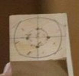
Both ends of the work piece were marked out with a
centre-point and straight lines joining the centres (not the corners) of
opposite sides.
Then a circle is drawn such that where it crosses the straight lines, these
become the contact points for the drive & tail centres.
Care must be taken to ensure they are not too close to the edge of the finished
piece or else the centres will not have enough grip to support.
With a compass centred on these four new points, draw arcs of the same radius to
guide where the final edges will end up.
(The greater the radius, the more pronounced the angles at the corners will
be)
Finally, number the four arc centres of one end (1 - 4) clockwise and once
you've identified the corresponding number 1 on the opposite end, number these
arc centres anticlockwise!
It will save quite a muddle later on.
Ensure the lathe speed is set low and any tool rest is
well out of the way before mounting the work piece.
Using
● a Spring Steb DRIVE Centre &
● a Spring Steb or Revolving Ring TAIL Centre,
mount the work piece onto the lathe with drive & tail points on the arc centres
marked 1.
The work will be offset so check that it clears the tool
rest when the piece is rotated by hand.
With it out of balance you need to carefully adjust the lathe speed up until
just before vibration starts to intensify.
Remember to stop the lathe if you need to readjust the tool rest.
Smoothly take off the one side with a roughing gouge.
(It's important not to push the gouge into the piece; just along the piece
with the handle down to keep the cut gentle)
Check for a level surface as you turn away down to near the final edge marks drawn on
the ends.
Sand using abrasives on a block just gently kissing as the lathe slowly turns.
Finish off each grit along the grain with the lathe stopped.
Repeat with centres marked 2, 3 and 4.
You might need to re-mount some of the centres to trim faces straight, even &
level.
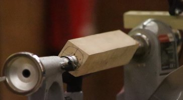
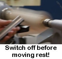
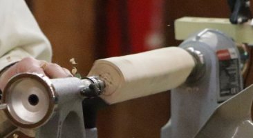
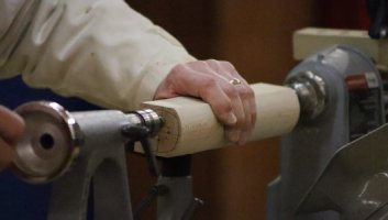

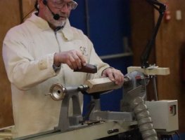
¤ Twisted Spindle
The ends were marked out as above with the sole exception that once one end
is marked 1 to 4, the corresponding number 1 on the other end must be one hole
further round.
Once again, one end must be marked 1 - 4 clockwise while the other end marked
anticlockwise.
Thereafter, work as above to smoothly turn off each side.
With eccentric turning, speed is your friend because the untouched section moves
pass the gouge tip quicker so there is less tendency for the gouge to 'fall
inwards' before the touched side comes around again.
A shadow will appear at the top of the piece; you should work to get that shadow
parallel to the lathe beam.
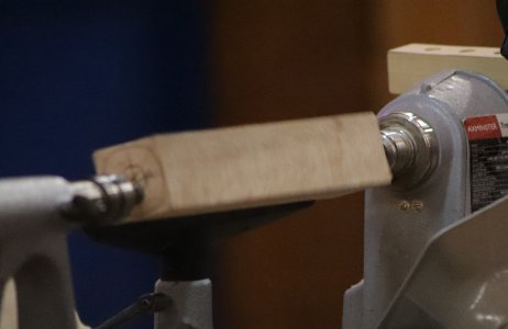
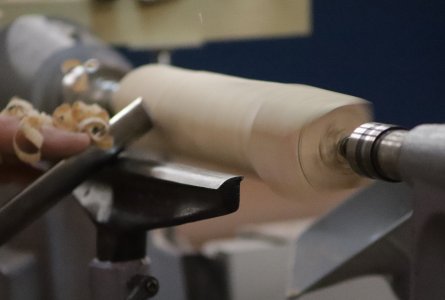
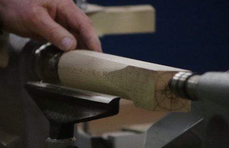
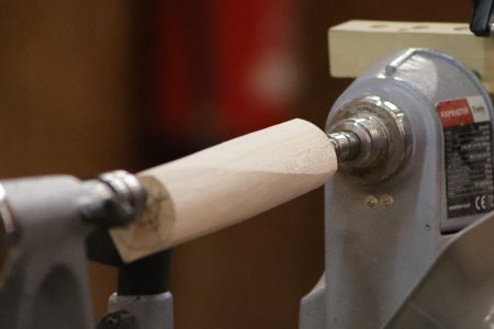
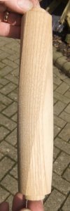
Sanding with the lathe stopped may be more effective with applying the grits
along the grain.
You might need to re-mount some of the centres to trim faces evenly.
¤ Oval Handle
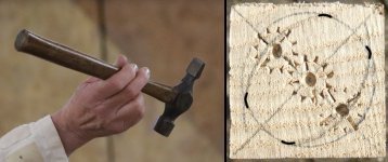 The
reduced curves of the flatter faces will need a larger radius than the radius
used from the centre of the work piece.
The
reduced curves of the flatter faces will need a larger radius than the radius
used from the centre of the work piece.
This may cause the offset centres to be near or even outside the finished cut.
Consequently, both ends of the work piece must be left uncut with enough length
to ensure there is sufficient strength to support the drive & tail centres.
Remember to allow for this when selecting work piece length.
Marking up in this case benefits from drawing straight lines from the
diagonals (to find the overall centre); draw a circle (which will
become the widest dimension).
Then mark 2 arc centres equidistant from the work piece centre such that the
drive & tail centres will have enough support up into the corner of the piece.
Draw in the arcs within the previous circle (to guide where the final edges
will end up).
Take care that your centre marks on the other end correspond to the same
diagonal!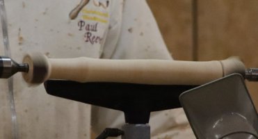
The piece was mounted between centres and a parting tool used to delineate
the ends of the finished handle to the depth of the widest dimension.
With a roughing gouge, a cylinder was formed to include any shaping required (eg
curves for a handgrip) using the parting tool depth marks as a guide to the
minimum size to turn away.
The cylinder was sanded through the grits.
The parting tool was then used again to reduce the spigot end-delineations to
the depth of the guide arc on the end of the piece.
It was now mounted using the offset centres.
The same principles of tool rest positioning, lathe speed and smooth tool use
were applied as highlighted above.
The newly reduced sized spigots showing up in the shadow of the turning piece
now acted as a guide to how much to turn away each face.
The piece was sanded using abrasives on a block just gently kissing as the lathe
slowly turned;
each grit finished off along the grain with the lathe stopped.
Then repeated using the other offset centres.
Be prepared to re-mount to one/both of the offset centres to get the faces even.
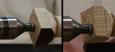
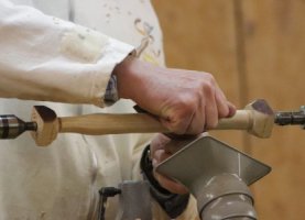
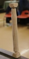
¤ Cabriole Leg
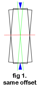
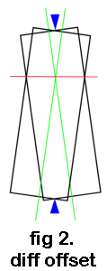
First, we need to think of what happens when we offset in opposite directions
from the overall centre.
Imagine a block of wood revolving and the shadow resulting will resemble the
drawings here.
In figure 1, the amount of opposite offset at either end is the same;
In figure 2, there is a larger offset at the bottom.
The red line defines where there is no shadow and the piece appears stationary.
For want of a better name of something on a leg, let's call this the 'knee'.
You can see that the greater the difference in offsets at each end, the 'knee'
moves closer towards the smaller offset end.
When turned away from the knee downwards, this will produce an elegant shape for
a cabriole leg.
Whether the cabriole leg is for a seat or table top, its helpful to leave the
top few inches as a square to aid attachment.
Feet are traditionally set on the diagonal so they face part forward and part
outwards & look more stable.
Marking up the ends involves drawing in the diagonals to find the overall
centre.
A very small offset should be marked on the top but on the bottom end, mark a
larger offset on the same diagonal but the opposite side of the overall centre.
Remember to make a note of these offset distances for making matching legs.
Mounted between overall centres, Paul used a skew to cut a 'V' about 2" from
the planned top end and deep enough to mark all four edges.
A roughing gouge turned away a cylinder from the 'V' cut down to the bottom end.
A bead was formed with a skew, spindle gouge or beading tool to tidy the V under
the top square.
The planned bottom end was marked out for :-
● where the leg would touch the floor,
● widest part of the bead that the foot would stand on,
● widest part of the foot.
The piece was mounted between offset centres.
Working from the 'knee' towards the bottom, Paul turned away the shadow as far
down as the widest foot pencil mark.
The piece was reverted back to centrally mounted to form the foot and the floor
bead immediately below it.
The foot area and the knee areas were sanded as described previously.
Then while mounted between the offset centres, the knee to foot areas were
sanded.
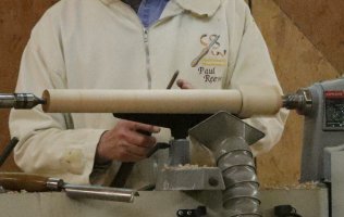
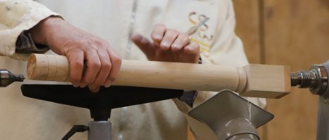
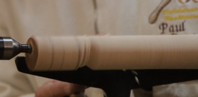
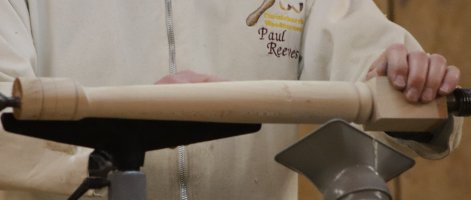
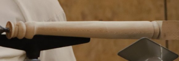
(photos by
Mark Codling)
<to
index>
John Bolt
Demonstration of Podlet turning
Thu, 19th December 2019 at MWCC Club Night
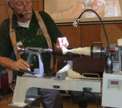
Podlets are a name generally given to small
thin wooden flower-like structures.
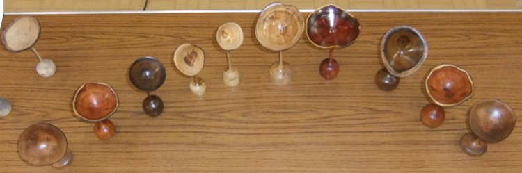
The choicest wood to select is wet/green, is of reasonable
length to enable a degree of bend of the stalk; most with light or dark colours
work well. Natural edges look fine but it would not be a problem if
all/some is missing (as explained below).
Another consideration is that the base be heavy enough to stably support the
finished piece.
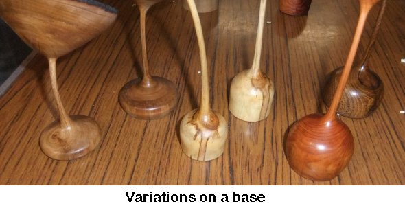
Bear in mind :-
● The piece will start off being supported between centres and that both ends
will need to be squared off.
● The roundest end is better for the petal & supported in the tailstock; the
drive end will eventually be trimmed as per your chuck spigot for supporting
while hollowing out
the petal and turning the stalk.
● Ideally, for strength reasons, you want to avoid the pith anywhere inside the
finished stalk. Choosing a piece with an off-centred pith (eg horizontal branch
with a large area of reaction wood above) would be ideal but otherwise,
purposely plan to offset the centres such that the pith lies about 10mm from the
stalk and so will end up being cut away.
● The tailstock will be removed for hollowing the petal but needs to support the
piece when turning the stalk;
so a ring or cone live revolving centre would be the best to use.
While in between centres, start off at a slow
turning speed as the piece will probably be out of balance.
Keeping the bark on the top end of the petal, even off the rest of the piece, which will
gradually allow you to up the speed.
Start a shallow hollowing of the petal & form a spigot for your chuck at the
drive end.
Mount on your chuck & continue hollowing with a smaller gouge (to avoid
excessive vibration without the support of the tailstock) to a depth of at least
an inch.
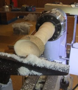
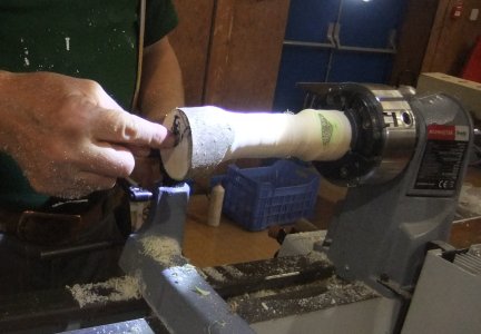
Once the inside is completed, finish with
abrasives before continuing with the stalk & base.
Wet/Green wood tends to become fluffy and clogs the abrasive - problem reduced
with wet sanding (i.e. dip abrasive into water)
Tailstock now returned into position but with
some matting material to protect the contact area within the petal.
Trim back the bark towards the lip of the petal; if one side of the lip ends up
too thick (perhaps due to avoiding the pith), an option is to reduce the
protruding edge back into the round and then decorate the edge with a
pyrographic tip.
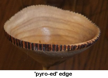
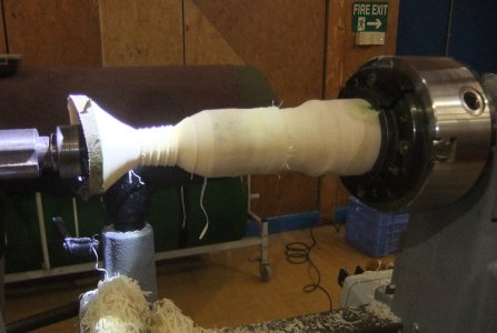
Working towards the headstock about an inch
at a time, turn out the stalk and sand finish as you work along while the
strength of the piece is supported from the drive end. John used a
homemade Velcro-ed piece of plywood with various grits in order to even out the
stalk as he progressed, making sure (where the stalk was particularly thin) to
support the opposite side with his fingers.
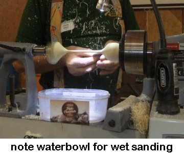
Plan ahead where the piece will be parted off
and thus where the start of the base should be.
The piece will look better with the base being a smaller diameter than the
petal.
Reduce the base to desired diameter and shape to blend the curves.
Wet wood will naturally dry out and distort
the piece.
For a more controlled process, one can microwave the piece with a heavy
microwave-safe mug/bowl resting on the stalk.
After the one time he tried this method & the lady in the house expressed
concerns of smells from the kitchen, John now uses steam from a kettle on a gas
ring applied for about 4 or 5 minutes via a hose with a split in one end.
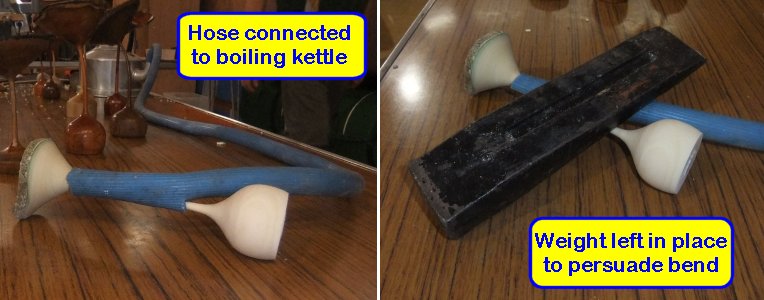
There is a helpful video on line <HERE>
<to
index>
Paul Reeves
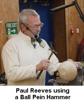 Demonstration of Texturing
Thu, 21st November 2019 at MWCC Club Night
When Paul asked his audience what they regarded as texturing, a few voiced it
meant spoiling a lovely flat surface!
Paul had in mind something like, "Enhance a surface with interest or
appeal."
Not only visually but (perhaps more importantly) in a tactile way.
Putting on Texture improves a plain grain wood with contrast. For example,
applying a band of indentations about an inch below the outside rim of a bowl
(where one's hands will invariably grip the piece) adds to the enjoyment.
There are four ways of applying texture :
● Both held tool and piece stationary;
● With the piece turning and a simple tool on the tool rest;
● Using a rotary tool with the piece held still;
● With the piece turning and using a rotary tool.
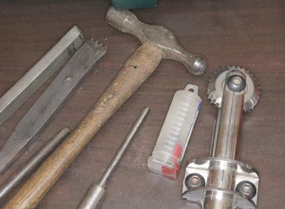
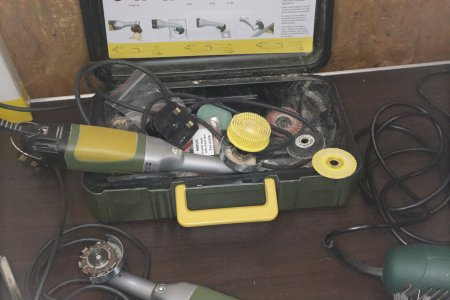
It is not necessary to have lots of texturing tools.
Simple Tools include :
Ball Pein Hammer
Straight Metal Bar with a domed head (Tip: avoid any
with sharp edges)
Hole Punch (Tip: smaller punches
make colour tints look better)
40 Grit Abrasive! (Tip: but keep it moving)
More Sophisticated Hand Tools :
Thread Chaser
Chatter Tool
Coarse Hand Knurl
Sorby Texturing & Spiralling Tools
Henry Taylor Decorating Elf
Power Tools include :
Angle Grinder (eg Proxxon)
Electric Drill (eg Dremel)
Power Carver
Techniques :
With the percussive tools, indent edges should meet while flat areas between indents
be kept as small as possible. It is hard to be random but
for the best effect, all indents should be kept of similar size and the same
should apply to the spaces between. To keep
depressions even, side grain areas will require slightly softer hits while end
grain areas will require slightly heavier. Hole Punches & Metal Bars tend
to need harder hits, particularly with harder woods.
When applying a band of texture, it is helpful to define
borders for the band with grooves. This is achieved with a round skew, a
parting tool or even the point of a gouge; all placed so as to mask any marks
outside the originally intended border line. Any wayward indents remaining
outside might be recovered with judicial use of woodturners spittle!
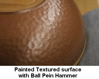
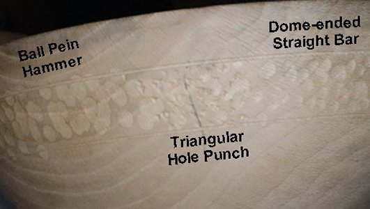
A change of the lathe speed will result in different effects.
With powered tools, the higher the lathe speed, the less regular the
texturing while with the piece turning slowly or stationary, the cleaner the effect.
The opposite applies with the speed of the cutting tool - the faster the speed
of the drill, normally the neater the finish.
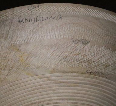
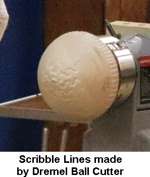
A common decorative texture is Fluting.
These are best created using powered tools with accessories such as Ball Cutter,
Chain Cutter, Flat Disc or Power Carver.
If applied with the lathe turning - present the tool in line to the rotation of
the piece.
If applied with the lathe off - move the tool in the direction against the
cutter's rotation.
The Power Carver tends to produce the smoothest fluting.
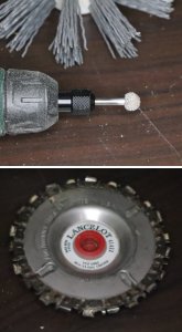
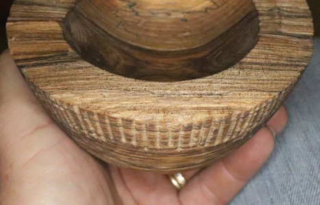
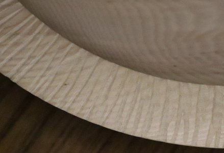
Once your texturing has been applied, you will probably need to tidy up the
edges and clear away the 'hairy' bits.
Whether using a bristle brush by hand or a rotary tool with a brush attachment,
move the brush in the same direction as the line of pattern.
A Blow Torch can be used to burn off hairy bits but should only be used if
leaving as burnt decoration or if colouring with something which will cover up
the inevitable scorch marks.
(photos by
Mark Codling)
<to
index>
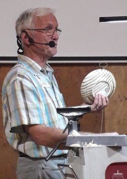
August
2019
- Demo 3
Working Plywood with Ed
Walker
It was surprising to learn that the Egyptians used plywood
some 3500 years ago; the Royal Navy used several laminated layers of hand-sawn
veneers at the end of the 18th Century; and in 1847 Sweden, Immanuel Nobel
(father of Alfred) realised that several layers of wood bonded together was
stronger than a single thick layer and subsequently, he invented the rotary
lathe to exploit plywood's industrial potential.
Ed went on to describe the types of plywood in increasing price : Softwood made
from Cedar, Firs or Spruces; Hardwood from Oak, Beech or Mahogany; Tropical from
wood as the name suggests; Aircraft grade incorporating adhesives resistant to
heat and humidity (most memorably used in the WW2 De Havilland Mosquito
aircraft); Decorative grade made from thin veneers of attractive woods; and
Marine grade made from tropical hardwood with few defects and waterproof glue.
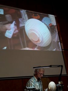 It
was startling to see how many holes and flaws occurred within the cheaper
grades, all requiring copious amounts of superglue and wood dust to stabilize.
It seemed as if the better quality plywood grades wouldn't be much more
expensive than the Softwood plus all the superglue!
It
was startling to see how many holes and flaws occurred within the cheaper
grades, all requiring copious amounts of superglue and wood dust to stabilize.
It seemed as if the better quality plywood grades wouldn't be much more
expensive than the Softwood plus all the superglue!
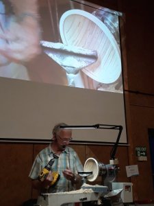
Ed discussed particular aspects to consider when working with plywood :-
►Let your glue
have plenty of time to really set before turning, eg overnight;
►Coloured plastics
may be used as laminates but roughen the plastic sheets for the superglue to
adhere;
►If using a
doughnut ring with your chuck, glue an appropriately sized sheet of ply under
the ring for a flat & secure contact;
►If using a tail
stock, avoid a pointed centre splitting the laminates of the ply by either
gluing a sacrificial piece of wood/ply for the pointed centre to engage or else
a ring type revolving centre;
►Gouges will blunt
quickly but shear scraping works well;
►With plastic as
laminates, watch buffing speed as too much heat will soften it;
►Axminster supply
resin-impregnated coloured wood veneers.
The September 2019 Competition was set for a
turned piece(s) comprising at least 50% of a ply component.
<Competition
Results>
<to
index>
October
2019 - Demo 4
Handles & Feet
with
Graham Turner

Handles & feet on wood-turned pieces benefit from being curved
themselves.
Apart from carving, which is not a technique many woodturners have mastered, the
Turner's solutions were twofold :-
Either
turning a hollow form, then band-sawing into segments to produce several
identical pieces;
or
(taking a leaf out of the last demonstration with Ed Walker), creating a
laminated piece and steaming into shape against a prepared shape former.
A practical wood for steaming is Ash. Graham had built up
laminates from 2.5mm Ash veneers (referred to as Constructional Veneers)
interspersed with 0.7mm Wenge veneer for contrasting colour.
Photos 2 & 3 below demonstrate two differently shaped formers.
Both produce flattened curves, but if desired, could be mounted between centres
and their side edges rounded off.
Graham's example was a flat offset base (as in photo 3) with a cylindrical
handle subsequently rounded off between its centres (as in photo 4).
Great care must be taken to ensure the flat base doesn't foul the tail stock
while turning the handle.
The turner's fingers are also vulnerable so Graham prefers to put his guiding
hand under his gouge rather than over the tool rest.
Steaming was accomplished in Mrs Turner's Vegetable Steamer for
about 5 minutes immediately before bending and clamping against it's shape
former.
(It wasn't made clear whether Mrs Turner was aware of this usage but Graham did
wash it out afterwards; so that will be all right then!)
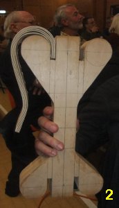
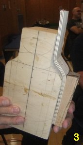
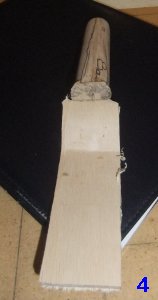
Graham then demonstrated a method for producing feet for a
piece.
Always enjoying humour in his turning, Graham took the literal sense of feet.
Starting with a piece of Walnut with a hole through one end using a 25mm
Forstner, he turned a lip at the tail end before hollowing out to leave about a
10mm thick wall, (photos 5 & 6).
Using an indexed chuck to delineate every 30
°
so that a bandsaw could cut an individual leg (photo 7), a parting tool cut was
made just
above the depth of the hollow so that each segment could be easily broken off
the round, (photo 8).
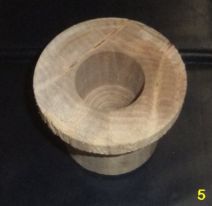
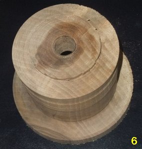
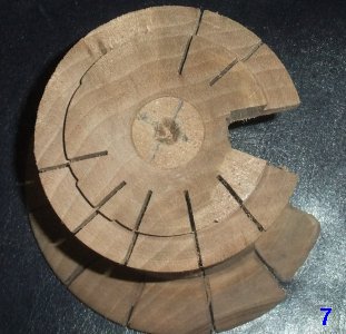
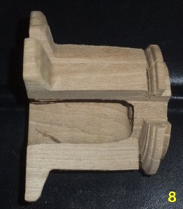
Each 'foot' was placed between a ring drive centre (for better drive support) & tail stock to shape the leg
muscle
A microplane was used to round off the toe & heel areas before back to the
bandsaw in order to form individual toes, (photo 9)
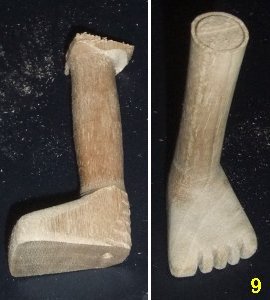
A similar process can be employed for making handles that connect at both ends.
Photo 10 shows the various stages.
With careful design, this system allows for the connecting ends to line up flush
with the outside of your turned hollowed vessel to help with a larger gluing
surface.
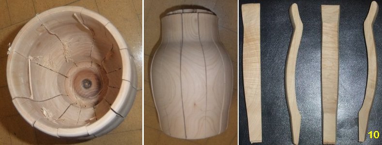
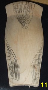
Other options allow different handle shapes; for example, double joint at the
top with a single connect at the bottom, (see photo 11)
It is important to consider the direction of the wood grain in order to preserve
strength.
Handles designed with large curves are likely to have a weak section of end
grain somewhere while shallow curved handles with grain from one end to the
other will have more integral strength.
Choice of close grain woods like Walnut, Maple also contribute to strength.
The November Competition was set for a
turned piece(s) comprising an attached handle and/or foot.
<Competition
Results>
<to
index>