![]()
Pencil
Shooter
with
Paul Reeves
Thu 16th January 2025 at MWCC Club Night 
The forceful characteristic needed to
propel a pencil is stretchiness, which can be obtained from elastic bands or springs.
The majority of online examples rely upon sawn shapes to provide strength for
supporting the stress & forces involved with taut rubber bands but as
Woodturners, we want predominantly turned components.
For this demonstration, Paul had chosen to use the energy provided from
releasing a compressed spring to fire a hexagonal pencil (doesn't
have to be a Reeves
pencil of course!) that is no larger than 8mm diameter.
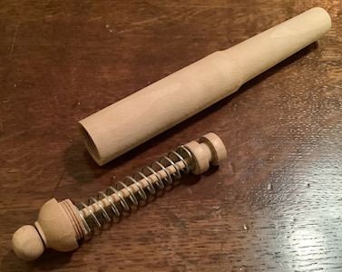
The 'weapon' shown below comprises of a Barrel with 2 bore sizes to accommodate
the 8mm pencil through the Muzzle end and 18mm bore through the Breech end. The
firing mechanism is a combination of Piston (with a notch for a trigger), the
Spring and a Rod through the Breech Cap to the Knob, which holds everything together.
Barrel
Taking account of the length of his
Spring and about another 100mm of Bore to keep the pencil's flight true, Paul
had selected a minimum 200mm length of 35mm square blank of Beech for his
Barrel.
Mounted between centres, a Spindle Roughing Gouge turned it to a cylinder
suitable to be mounted in his 38mm o'Donnell Jaws. With the piece firmly gripped
in the jaws and a tailstock in support, a Skew Chisel squared off the end in
readiness for the Breech component to be a screw tight fit.
The tailstock was refitted with a Jacob's Chuck and an 18mm saw-toothed Forstner
bit, chosen because it was just bigger than the diameter of the Spring. The lathe speed was reduced and
while starting off carefully with the bit exactly centred, a hole was drilled deep enough to
accommodate the sum of the Piston & Spring lengths plus about 8mm for the
Breech's thread to screw into the Barrel. Once the first hole is done,
further turning & drilling will be easier to keep true.
Remember that handling a Jacob's Chuck does need care as highlighted in
our Top Tip <here>.
To reduce friction inside, the Bore was sanded smooth with abrasives wound
around a pencil.
Paul decided to enlarge the first
10mm or so of the Barrel so that the Spring/Piston mechanism would clear all
threads whenever inserted or removed; this only needed the
Bore to be increased about 2 or 3mm with a Box Cutter.
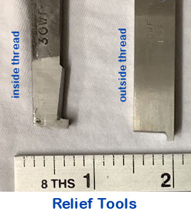 Next, a Relief Tool was used to
create a slot into the wall of the Barrel next to the step of the 18mm Bore
width. The thread is created with the Thread Chaser when it 'lands' and is
'taken off' in a smooth circular motion. That slot will allow freedom for the
Chaser to lift clear of the inside threads before it gets stopped suddenly
against the step down of width and would damage the threads already made.
Next, a Relief Tool was used to
create a slot into the wall of the Barrel next to the step of the 18mm Bore
width. The thread is created with the Thread Chaser when it 'lands' and is
'taken off' in a smooth circular motion. That slot will allow freedom for the
Chaser to lift clear of the inside threads before it gets stopped suddenly
against the step down of width and would damage the threads already made.
Beech doesn't often take a thread as well as some closer grain woods but in this
demonstration, a perfectly good thread was obtained with just half a dozen
passes without having to resort to wily ploys like stabilizing the wood grain
with thin superglue. The thread and bore were checked and any roughness
was dealt with by brush or abrasives.
The piece was reversed in the chuck
to expose the Muzzle end and aided by the tailstock, lined up for the Jacob's
Chuck (now fitted with a sharp 8.5mm drill bit) to drill its hole down the
centre. As previously, start drilling slowly before speeding up, watch for
clogging up and clear out frequently until certain that you have drilled through
to the 18mm bored hole.
Paul then used a countersink in the Jacobs to create a chamfer in the Muzzle
Bore. This will help later when the Breech Cap is completed and screwed on such
that the Barrel can be held between centres. Again, to reduce friction, this end
of the Bore was 'polished' using a drill bit in a powered drill.
Breech Cap
Taking another piece of Beech
already prepared to a cylinder and clamped true in the o'Donnell jaws, Paul used
a Parting Tool to form a parallel spigot with a diameter slightly bigger than
the enlarged Breech Bore. This spigot will take the male thread that will engage with
the Barrel thread already cut.
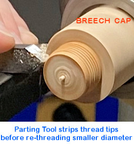 The oversize start permits a thread to be
established and then by trimming the thread tips away, there is enough for the
Chaser to easily engage and re-cut the threads which will eventually reduce the
diameter to fit the female thread in the Breech Bore.
The oversize start permits a thread to be
established and then by trimming the thread tips away, there is enough for the
Chaser to easily engage and re-cut the threads which will eventually reduce the
diameter to fit the female thread in the Breech Bore.
Similar to the previous Thread Chaser preparations, you will need to use the
Parting Tool to slightly lower the level at the front of the spigot and at where
the spigot meets the bulk of the cylinder, in order that the Chaser has room to
come away from the threads before it barged into the edge of the cylinder.
This time, the Chaser is lifted out of the threads by lowering its handle while
moving in the smooth circular motion.
With the lathe speed reduced, new threads were produced and checked against
those in the Breech Bore before being trimmed back parallel again and again until
eventually they fitted into each other. Bear in mind that the top of the threads you are creating
at this step, need to end up in the
bottom of the threads you left in the Barrel.
This time, Paul did need to
reinforce the threads by pouring very thin superglue onto them while keeping
the piece moving round in order to avoid pooling and allowing enough time for
the glue to be drawn into the pores and harden before attempting to re-thread.
Only 2 or 3 threads are needed for the Breech Cap to grip the Barrel so once the
threads were matched, the length of the spigot was trimmed back accordingly with a Parting Tool and the thread depths carefully cleaned up with
400 grit abrasives.
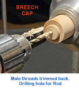
A centre mark was made on the end where a hole for the Rod to slide freely
through the entire Cap was drilled using the Jacob's Chuck. Paul planned to use
a 4mm dowel of Bamboo so this hole needed a 4.5mm drill bit. Finally, after
allowing enough for space for the curve of the Breech, the piece was parted off
square and the drilled through hole was sanded/polished to aid free movement.
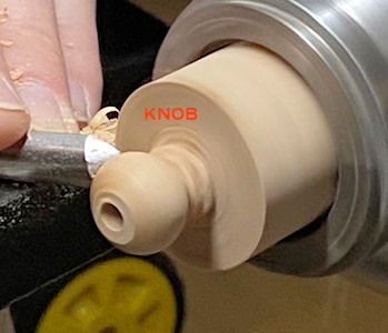
Knob
The next component was the Knob for pulling with your fingers to compress the
spring. Being able to finger grip this component dictated how big to make
its diameter but once determined, this was a simple shape for a Spindle Gouge.
It then needed a 4mm hole to grip the Rod (this time not going all the way
through). The component was sanded as required, the end squared off with a Skew
before being parted off and the rest of the curve sanded back.
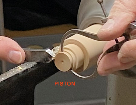
Piston
With a fresh blank in the o'Donnell jaws and callipers set to 17mm
(for a smooth travel within the 18mm Breech Bore) about 20mm length of cylinder
was gradually turned to 17mm diameter using the callipers as shown above.
As Paul was considering using a trigger to release the compressed spring, he
fashioned the Piston as shown in the first photo.
The Barrel was presented to the component on the lathe to check for fit before
the 4mm drill in the Jacob's Chuck drilled a hole of at least 10mm for the Rod
to be eventually glued in; Paul had considered to drill completely through
because this component wouldn't be visible and a hole would allow glue to be
applied to the end of the Rod. The piece was sanded and parted off.
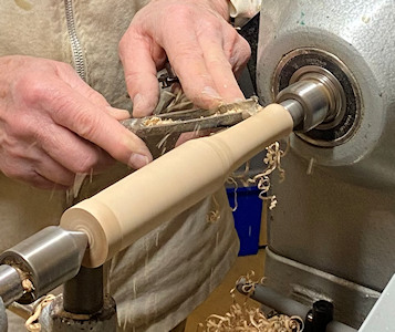
Shaping the Barrel
Prior to final assembly of the firing mechanism, the Breech Cap was screwed into
the Barrel and then mounted between a Light Pull Drive Centre and a Tail Centre
making use of the drilled holes at each end. A Spindle Roughing Gouge was used
to create a pleasing shape. The curve of the Breech was formed to the shape as
shown in the first photo and the piece was sanded through the grits as
necessary. Any additional decoration could now be applied as desired.

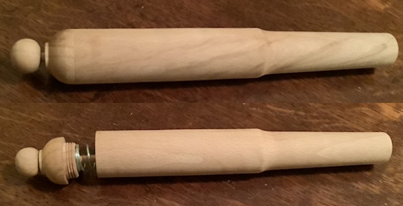
Assembling
After one end of the Rod had been glued into the Piston, its precise length
could now be determined by assembling the Spring and the Breech Cap, screwing
the Cap into the Barrel and while feeling the Piston against the 8mm Bore, mark/cut the extended Rod at whatever was the depth
of the drilled hole in the Knob. It's probably more sensible to remove the
firing mechanism from the Barrel so the Cap can be held against the Spring while
the Knob & Rod are glued in order to avoid any surplus gumming up the Cap.
Rules for this Competition :-
● The piece will be judged on it's aesthetic appearance;
● It must be capable of propelling the provided pencil;
● The Club will provide 8mm hexagonal pencils with a rubber one end &
blunt the other;
● Powered by Spring/Elastic/Bungee/Compressed Air etc; (Chemical reactions
prohibited!)
● No restriction on size of Shooter.
● The Shoot-Off will be an entirely separate Target Competition from
a table top and its
Rules will be explained on the Night.
The January 2025 Competition was set to create a Pencil Shooter(s) of predominantly turned components that can propel a pencil.
(photos by Andy Ogilvie, Rick Patrick & Paul Reeves)